Rotary switch
The LMC has a rotary switch that makes it possible to switch between:
•
Remote control;
•
Local control.
For more information on the rotary switch, see §
.
External temperature probe
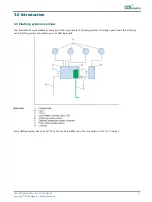
One external temperature probe per flashing system must be installed onto any equipment cabinet in the system. The LMC
reads the data from the external temperature probe and uses the data to control the anti-condensation heating resistors. The
temperature probe reads the actual ambient temperature.
Start-up and scanning
At start-up, the LMC reads its local memory to find the system configuration. Then, the LMC contacts all the FCU PCBs in the
flashing system through the local bus. Then, the LMC sends system configuration data to each equipment to program them
for normal operation.
After the start-up sequence, the LMC continues to scan all the FCUs sequentially to ensure correct operation. If the system has
RTIL flashers, they are scanned at a higher rate because it is required to switch one OFF if the other fails (misfires).
Synchronization
The LMC synchronizes all equipments to make sure that they flash in a correct flashing rhythm.
To do this, the LMC sends a message to all equipments at regular intervals.
3.6 Options
Remote control between flashing system and tower
Each equipment can be controlled remotely with Multiwire, J-Bus, or a combination of the above. See §
Over-voltage protection
The equipment can be supplied with an extra over-voltage protection. When an overvoltage is supplied to the individual
equipment cabinets, the over-voltage protection activates. An alarm can be generated through the feedback of the LMC.
When the origin of the problem is solved, it is necessary to replace the MOV cartridge.
Dongle
The dongle enables you to connect the equipment directly to a PC. A special configuration software tool makes it possible to
monitor and control the complete flashing system that one LMC controls.
When the dongle is connected between the system and a PC, the PC takes over the control of the flashing system. In this
case, the dongle collects all the necessary data from the LMC and the individual equipments. When the dongle is connected,
it also provides the synchronization messages instead of the LMC.
3.7 Remote control description (option)
J-Bus
The J-Bus interface uses a single or dual databus(es) to allow remote monitoring of a bigger quantity of parameters.
•
With a single databus, the equipment has only one communication channel.
•
With a dual databus, the equipment has two communication channels: Bus A and Bus B.
The communication channels must take different routes to avoid a communication failure if one cable is interrupted.
Multiwire PCB
A multiwire PCB has 2 times 12 terminals. The terminals handle the maximum 8 incoming and maximum 8 outgoing signals
between the equipment and the remote control system.
There is only one multiwire PCB possible per LMC, so also one multiwire PCB per flashing system.
Flashing System Maintenance
Introduction
16
Copyright
©
ADB Safegate, All Rights Reserved
Summary of Contents for FCU-1-in-1
Page 2: ......
Page 8: ...Flashing System Maintenance TABLE OF CONTENTS viii Copyright ADB Safegate All Rights Reserved ...
Page 18: ...Flashing System Maintenance Safety 8 Copyright ADB Safegate All Rights Reserved ...
Page 28: ...Flashing System Maintenance Introduction 18 Copyright ADB Safegate All Rights Reserved ...
Page 42: ...Flashing System Maintenance Commissioning 32 Copyright ADB Safegate All Rights Reserved ...
Page 64: ...Flashing System Maintenance Maintenance 54 Copyright ADB Safegate All Rights Reserved ...
Page 106: ...Flashing System Maintenance Technical data 96 Copyright ADB Safegate All Rights Reserved ...
Page 110: ......


