4.0 Commissioning
4.1 Main commissioning procedure
1. Remove the covers. See §
.
2. Configure the FCU PCBs. See §
3. Configure the flashing system. See §
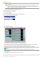
4. Configure the remote control interfaces. See §
Remote control configuration: multiwire (option)
5. Install the covers.
6. Test the equipment. See §
4.2 Configure the FCU PCBs
4.2.1 Set the communication parameters
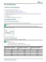
Set the dip-switches dip-switch bank SW1 of each FCU PCB. This is the factory setting.
Note
Do not change the setting as indicated in the illustration. First contact ADB if you want change this setting.
4.2.2 Define the equipment address
Each FCU PCB in the system must have its own, unique binary address.
Note
If RTILS (REILS) are present:
•
Configure an unique address to both REILS or RTIL units;
•
Make sure the REILS or RTILS have the highest binary and physical address.
Physical equipment
order
Binary address
Physical equipment
order
Binary address
Physical equipment
order
Binary address
01
100000
09
100100
17
100010
02
010000
10
010100
18
010010
03
110000
11
110100
19
110010
04
001000
12
001100
20
001010
05
101000
13
101100
21
101010
UM-4019_AM02-620e, Rev. 3.0, 2020/05/12
19
Copyright
©
ADB Safegate, All Rights Reserved
Summary of Contents for FCU-1-in-1
Page 2: ......
Page 8: ...Flashing System Maintenance TABLE OF CONTENTS viii Copyright ADB Safegate All Rights Reserved ...
Page 18: ...Flashing System Maintenance Safety 8 Copyright ADB Safegate All Rights Reserved ...
Page 28: ...Flashing System Maintenance Introduction 18 Copyright ADB Safegate All Rights Reserved ...
Page 42: ...Flashing System Maintenance Commissioning 32 Copyright ADB Safegate All Rights Reserved ...
Page 64: ...Flashing System Maintenance Maintenance 54 Copyright ADB Safegate All Rights Reserved ...
Page 106: ...Flashing System Maintenance Technical data 96 Copyright ADB Safegate All Rights Reserved ...
Page 110: ......


