4.5 Remote control configuration: J-Bus (option)
Note
Use the configuration software tool. See chapter 8 .
4.5.1 General procedure
1. Set the binary address of the LMC.
2. Set the slave address.
3. Set a two or four wire communication type.
4. Check the connection.
4.5.2 Set binary address of LMC
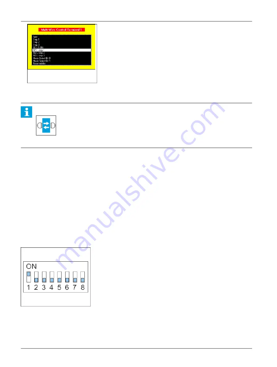
Set the dip-switches of dip-switch bank SW1 according to the databus connection of the equipment cabinet. For details see §
Local Master Controller (LMC) - PCB1513
4.5.3 Set slave address
The slave on the databus must have a unique binary address.
Change the settings of the dip-switches of dip-switch bank SW1 on the LMC PCB.
4.5.4 Set two/four wire communication
Set the straps on the LMC PCB. See §
Local Master Controller (LMC) - PCB1513
.
Flashing System Maintenance
Commissioning
28
Copyright
©
ADB Safegate, All Rights Reserved
Summary of Contents for FCU-1-in-1
Page 2: ......
Page 8: ...Flashing System Maintenance TABLE OF CONTENTS viii Copyright ADB Safegate All Rights Reserved ...
Page 18: ...Flashing System Maintenance Safety 8 Copyright ADB Safegate All Rights Reserved ...
Page 28: ...Flashing System Maintenance Introduction 18 Copyright ADB Safegate All Rights Reserved ...
Page 42: ...Flashing System Maintenance Commissioning 32 Copyright ADB Safegate All Rights Reserved ...
Page 64: ...Flashing System Maintenance Maintenance 54 Copyright ADB Safegate All Rights Reserved ...
Page 106: ...Flashing System Maintenance Technical data 96 Copyright ADB Safegate All Rights Reserved ...
Page 110: ......


