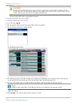
The procedure show how to replace these parts:
•
FCU-3 PCB at the left and the right of the equipment cabinet. See §
FCU-3 PCB at left or right of equipment cabinet
.
•
FCU-1 PCB and FCU-3 PCB in the middle of the equipment cabinet. See §
.
•
.
•
Multiwire PCB. See §
.
•
Multiwire cable. See §
•
J-Bus PCB. See §
.
•
Capacitor. See §
•
DC power supply. See §
.
•
Door micro-switch. See §
.
•
Local bus connection board. See §
.
•
Wiring assembly. See §
•
Cable entry kit with bottom. See §
•
Choke. See §
•
Mains filter. See §
.
•
Overvoltage protection (MOV). See §
Overvoltage protection cartridge (MOV)
.
•
Covers. See §
5.2.1 Required tools
•
Multimeter.
•
Standard electrical and mechanical tool kit;·
•
Screwdrivers with protection up to 1000 V;
•
Long screwdriver;
•
Spanner set (ring or socket spanners);·
•
Allen key 8 mm;
•
Magnet rod for collecting loose items;
•
Angle socket wrench;
•
Door key for the equipment cabinet.
Flashing System Maintenance
Maintenance
34
Copyright
©
ADB Safegate, All Rights Reserved
Summary of Contents for FCU-1-in-1
Page 2: ......
Page 8: ...Flashing System Maintenance TABLE OF CONTENTS viii Copyright ADB Safegate All Rights Reserved ...
Page 18: ...Flashing System Maintenance Safety 8 Copyright ADB Safegate All Rights Reserved ...
Page 28: ...Flashing System Maintenance Introduction 18 Copyright ADB Safegate All Rights Reserved ...
Page 42: ...Flashing System Maintenance Commissioning 32 Copyright ADB Safegate All Rights Reserved ...
Page 64: ...Flashing System Maintenance Maintenance 54 Copyright ADB Safegate All Rights Reserved ...
Page 106: ...Flashing System Maintenance Technical data 96 Copyright ADB Safegate All Rights Reserved ...
Page 110: ......


