5.2.2 Prepare: Switch OFF power supply
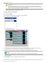
1. Switch OFF the main power supply at the substation.
2. Open the cabinet door.
3. Switch OFF the fused input switches (A).
•
FCU-1: fuse holders F1 and F2;
•
FCU-3: fuse holders F1, F2 and F3;
5.2.3 FCU-3 PCB at left or right of equipment cabinet
The procedure applies to the left and right PCBs of the FCU-3 cabinet. To replace the middle FCU board, see §
Remove base plate
1. Make sure that all power to the equipment is OFF. See §
Prepare: Switch OFF power supply
.
2. Remove the cover. See §
.
3. Disconnect all the connectors on the PCB. Use pliers for the connectors in TB3, if necessary.
4. Loosen the fasteners (A). Use an angle socket wrench for the nuts.
5. Remove the base plate (B).
6. Disconnect the cables from the two cable retainers (C).
Remove PCB from base plate
7. Loosen the nine nuts (A).
8. Loosen the two screws (B).
9. Remove the PCB. Use a lever below the board, if necessary.
UM-4019_AM02-620e, Rev. 3.0, 2020/05/12
35
Copyright
©
ADB Safegate, All Rights Reserved
Summary of Contents for FCU-1-in-1
Page 2: ......
Page 8: ...Flashing System Maintenance TABLE OF CONTENTS viii Copyright ADB Safegate All Rights Reserved ...
Page 18: ...Flashing System Maintenance Safety 8 Copyright ADB Safegate All Rights Reserved ...
Page 28: ...Flashing System Maintenance Introduction 18 Copyright ADB Safegate All Rights Reserved ...
Page 42: ...Flashing System Maintenance Commissioning 32 Copyright ADB Safegate All Rights Reserved ...
Page 64: ...Flashing System Maintenance Maintenance 54 Copyright ADB Safegate All Rights Reserved ...
Page 106: ...Flashing System Maintenance Technical data 96 Copyright ADB Safegate All Rights Reserved ...
Page 110: ......


