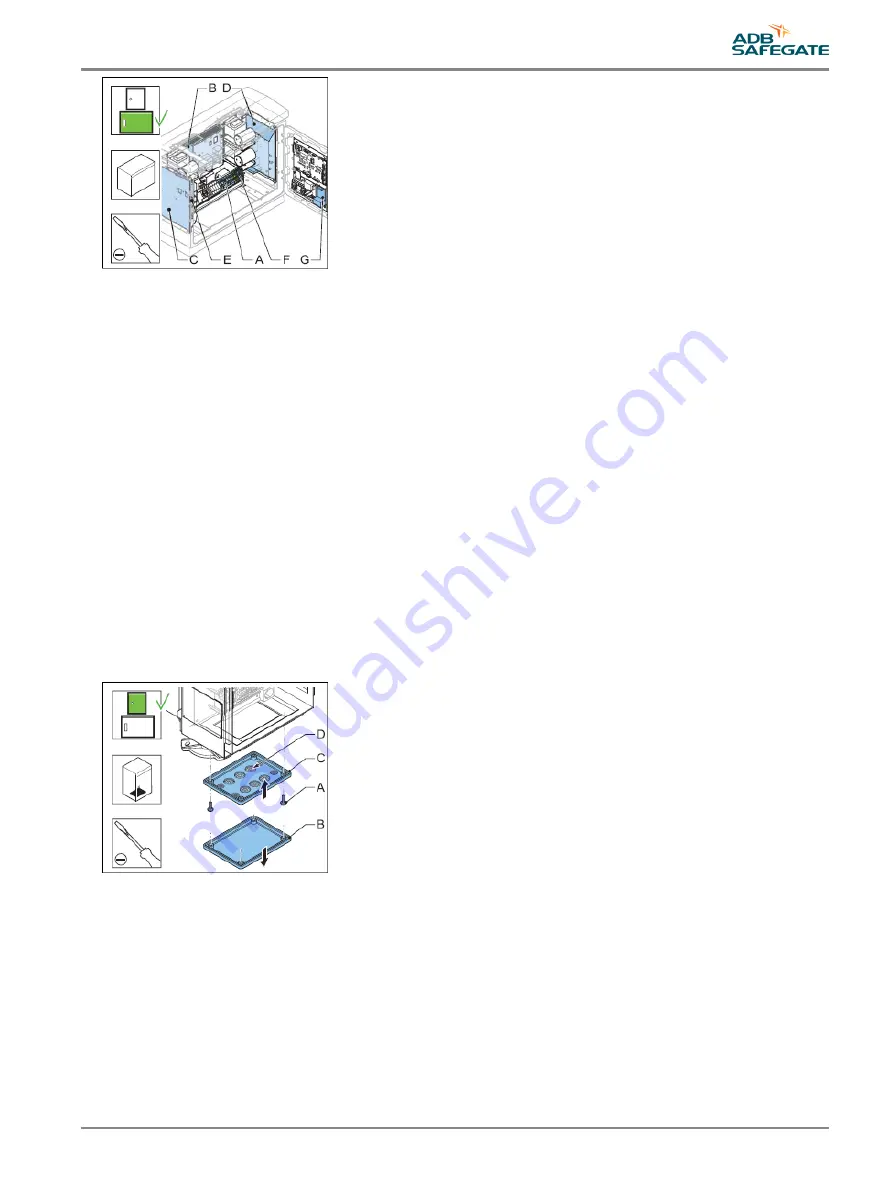
5.2.14 Cable entry kit with bottom
1. Make sure that all power to the equipment is OFF. See §
Prepare: Switch OFF power supply
.
2. Disconnect:
•
the flasher head cable;
•
the power input cables;
•
the local bus cables;
•
the optional LMC cables;
•
the optional remote control cables
3. Remove the four slotted screws (A).
4. Remove the bottom plate (B).
5. Install the new bottom plate (C).
6. Cut the glands of the bottom plate into an applicable size.
7. Put the cables through the glands (D).
8. Connect the cables.
9. Close the cabinet door.
5.2.15 Choke
The FCU-3 has three chokes. The FCU-1one choke.
1. Make sure that all power to the equipment is OFF. See §
Prepare: Switch OFF power supply
.
2. Remove the cover. See §
.
3. Remove the four screws (A).
4. Disconnect the cables from the FCU PCB connector TB4.
5. Remove the choke (B).
UM-4019_AM02-620e, Rev. 3.0, 2020/05/12
51
Copyright
©
ADB Safegate, All Rights Reserved
Summary of Contents for FCU-1-in-1
Page 2: ......
Page 8: ...Flashing System Maintenance TABLE OF CONTENTS viii Copyright ADB Safegate All Rights Reserved ...
Page 18: ...Flashing System Maintenance Safety 8 Copyright ADB Safegate All Rights Reserved ...
Page 28: ...Flashing System Maintenance Introduction 18 Copyright ADB Safegate All Rights Reserved ...
Page 42: ...Flashing System Maintenance Commissioning 32 Copyright ADB Safegate All Rights Reserved ...
Page 64: ...Flashing System Maintenance Maintenance 54 Copyright ADB Safegate All Rights Reserved ...
Page 106: ...Flashing System Maintenance Technical data 96 Copyright ADB Safegate All Rights Reserved ...
Page 110: ......


![Navig[8]r NAVBIKE-GPS User Manual preview](http://thumbs.mh-extra.com/thumbs/navig-8-r/navbike-gps/navbike-gps_user-manual_3574097-01.webp)


