2.7 Theory of Operation
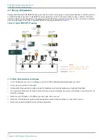
Background Information: RELIANCE IL uses power line carrier (PLC) technology to communicate between controlling units on
an airfield lighting series circuit. A RELIANCE IL system typically consists of one high voltage modem, or Master, collocated
with the Constant Current Regulator (CCR) powering the airfield lighting circuit and many slave units, or Remotes, collocated
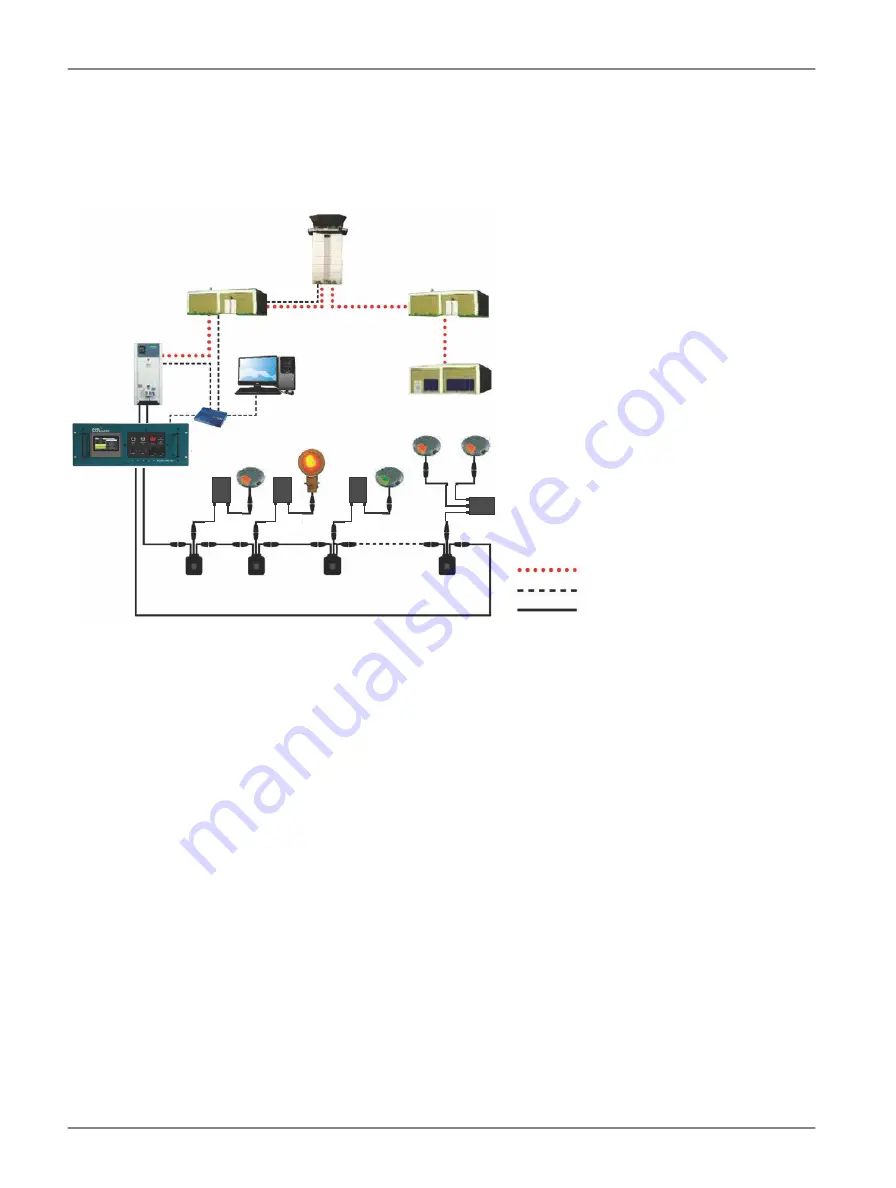
with individual lights in the field. A typical RELIANCE IL topology is provided in
.
Figure 6: Typical RELIANCE IL Topology
Commands from ATC (Fiber Optic)
Field communication (Ethernet)
Power line
Legend
Airfield Lighting
Substation
Air Traffic
Control
Airfield Lighting
Substation
Maintenance
Center
Constant
Current
Regulator
PC
Standard
Option
Hub
Master
Taxiway Centerline Lights
Elevated
Lights
Stopbar
Lights
Single
Remote
Dual
Remote
Series
Transformer
2.7.1 Main Characteristics and Figures
•
Up to 300 Remotes per circuit, providing a potential of 600 individually addressable lights per circuit.
•
Up to 20 km round-trip circuit length.
•
Configurable block evaluation modes include full feedback, small sample feedback, and optimistic feedback.
•
Can command 10 blocks to 10 distinct states with one powerline message. Can command all blocks to one state with one
powerline message.
•
Switches up to 600 lights, in 10 different groups, in less than 1 second.
•
Switches 5 stopbar/lead-on lights simultaneously and presents real-back indication in less than 1 second.
•
Status poll provides detailed Remote and lamp parameters.
RELIANCE Intelligent Lighting Platform II
RELIANCE Intelligent Lighting Master
16
Copyright
©
ADB Safegate, All Rights Reserved
Summary of Contents for RELIANCE Intelligent Lighting Platform II
Page 2: ......
Page 38: ...RELIANCE Intelligent Lighting Platform II Parts 32 Copyright ADB Safegate All Rights Reserved ...
Page 42: ......


