background image

2.7.2 Integrated System Control

Overall system configuration and control is realized via a control process with integrated web server for configuration and

maintenance.

Each circuit is equipped with a microprocessor-controlled Master for tracking, recording and management of state of all

Remotes in the circuit.

The Master communicates with all the Remotes (not light fixtures) in a circuit and polls all lamps independent from the

control system.

2.7.3 Architecture

Figure 7

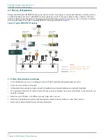
 depicts the general nature of the system components and their interactions. The “Control System”, shown in grey, is

an external ALCMS system that provides controlling commands and digests Master and Fixture status reports. There is

typically only one control system in the architecture. The “Master”, shown in blue, is the high voltage modem that

communicates commands to and receives status from the fixtures. There can be many masters in a given system. Masters

digest commands from the control system and provide status to it. Masters also communicate among themselves to maintain

communication timing synchronization. Each master communicates with the fixtures on its respective circuit.

Figure 7: Series Circuit Master / Fixture Architecture

96A0480, Rev. B, 2019/12/06

17

Copyright 

©

 ADB Safegate, All Rights Reserved

Summary of Contents for RELIANCE Intelligent Lighting Platform II

Page 1: ...RELIANCE Intelligent Lighting Platform II Master Control Device User Manual 96A0480 Rev B 2019 12 06 ...

Page 2: ......

Page 3: ...d are guaranteed to be merchantable and fit for the ordinary purposes for which such products are made ADB SAFEGATE L858 Airfield Guidance Signs are warranted against mechanical and physical defects in design or manufacture for a period of 2 years from date of installation per FAA AC 150 5345 44 applicable edition Note See your sales order contract for a complete warranty description All Products ...

Page 4: ...TE replacement parts or accessories Failing to make sure that auxiliary equipment complies with approval agency requirements local codes and all applicable safety standards if not in contradiction with the general rules Using materials or auxiliary equipment that are inappropriate or incompatible with your ADB SAFEGATE equipment Allowing unskilled personnel to perform any task on or with the equip...

Page 5: ...Control Unit 13 2 5 2 Rear View with Connections 14 2 6 Operation 15 2 6 1 Circuit Specifications 15 2 7 Theory of Operation 16 2 7 1 Main Characteristics and Figures 16 2 7 2 Integrated System Control 17 2 7 3 Architecture 17 3 0 Installation of stand alone RELIANCE IL Masters 19 3 1 Installation in the Control Cabinet 19 3 1 1 Power Supply 19 3 1 2 Connection to the Series Circuit 19 3 1 3 Over ...

Page 6: ...A 1 ADB SAFEGATE website 33 A 2 Recycling 34 A 2 1 Local authority recycling 34 A 2 2 ADB SAFEGATE recycling 34 RELIANCE Intelligent Lighting Platform II TABLE OF CONTENTS vi Copyright ADB Safegate All Rights Reserved ...

Page 7: ...o observe this warning may result in personal injury death or equipment damage ARC Flash may cause blindness severe burns or death WARNING Wear personal protective equipment Failure to observe may result in serious injury WARNING Do not touch Failure to observe this warning may result in personal injury death or equipment damage CAUTION Failure to observe a caution may result in equipment damage Q...

Page 8: ...y devices as specified by applicable safety regulations If safety devices must be removed for installation install them immediately after the work is completed and check them for proper functioning prior to returning power to the circuit Failure to follow this instruction can result in serious injury or equipment damage Additional Reference Materials Important Information IEC International Standar...

Page 9: ...rk is completed and check them for proper functioning Route electrical wiring along a protected path Make sure they will not be damaged by moving equipment Never operate equipment with a known malfunction Do not attempt to operate or service electrical equipment if standing water is present Use this equipment only in the environments for which it is rated Do not operate this equipment in humid fla...

Page 10: ...e properly trained and familiar with ADB SAFEGATE equipment are permitted to service this equipment An open airfield current circuit is capable of generating 5000 Vac and may appear OFF to a meter Never unplug a device from a constant current circuit while it is operating Arc flash may result Disconnect and lock out electrical power Always use safety devices when working on this equipment Follow t...

Page 11: ... Master Introduction RELIANCE Intelligent Lighting IL is ADB SAFEGATE s state of the art individual lamp control and monitoring system RELIANCE IL provides a radical leap in performance over prior airfield power line carrier systems The system is designed to communicate on the existing airfield series circuit power line without requiring separate dedicated cabling 2 2 1 Individual Lamp Control Mon...

Page 12: ...s a result of higher traffic throughput and better control of ground traffic movements Flexible routing functionality and safe operation under all traffic and environmental conditions resulting in reduced ATC workload Precise control of each segment of runways taxiways and stop bar lighting Adjacent lamp failure reporting Most economic solution for modernization projects through power line communi...

Page 13: ... of Stop Bar and Lead In Circuit Optional Runway Guard Light Remotes automatic start and net synchronous Wig Wag operation independent from Master meeting FAA requirements Firmware and application software can be downloaded into either the Master substation or Remotes field units State of the art diagnostic tools provide a quick overview about communication behavior Network management system provi...

Page 14: ...ax 8 W at 6 6 A Max 15 W for power supply 115 230 V Max 65 W on primary circuit at 6 6 A Description Remote Master Enclosure protection level IP 68 NEMA 6 P IP 20 LAN connection to upper control system IEEE 802 3 100 BaseT IEEE1588 PTP Net voltage of power supply 115 230 V AC 15 50 60 Hz MTBF 200 000 h 200 000 h Indicative MTTR 30 min 60 min Lightning protection 20 kA 8 20 micro sec 17 kA 8 20 mic...

Page 15: ...c characteristic needed in an equivalent L 824 cable Reuse of existing installations and layout with maximum cable length or number of lights to be verified Cable type specification L 824 Capacity of the cable 165 nF km 1 Inductance of the cable 0 20 mH km 1 typical impedance 125 kHz 35 Ohm Attenuation of the signal at 125 kHz 5 8 dB km 1 Length of serial circuit 20 km roundtrip 12 4 miles maximum...

Page 16: ...ft AGC2110 RELIANCE IL Master Wall Mount Door Open Right AGC3110 Ordering Code Remotes RELIANCE IL Single Channel Remote FAA Style 7 AGC4170 RELIANCE IL Single Channel Remote FAA Style 8 AGC4180 RELIANCE IL Single Channel Remote FAA Style 7 Initial Flash Off AGC4270 RELIANCE IL Single Channel Remote FAA Style 7 Initial Flash On AGC4370 RELIANCE IL Dual Channel Remote FAA Style 7 AGC5170 RELIANCE I...

Page 17: ...ant Current Regulator The CCRs are located within the Airfield Lighting Vault ALV They produce a constant current output to the airfield series circuit that light the airfield lighting fixtures RELIANCE IL Remote Master PC ADB SAFEGATE s trademarked abbreviation that describes the future proofing technology used to transmit and receive data across airfield lighting series circuit cabling Remote Un...

Page 18: ...same transport packaging must be used The number on the nameplate must be checked against the order number on the delivery note The nameplate Figure 2 is located on the side of the device example RELIANCE IL Master 30kVA Figure 2 Nameplate of the RELIANCE IL Master The address MAC ID of the Ethernet interface Eth0 and Eth1 e g Eth1 Address 0009CF8A 01D9 see Figure 2 should be recorded and will be ...

Page 19: ...ements have the following functions 1 Power On LED red Constant current regulator is switched on 2 Field Circuit Live LED amber System is running 3 Service 9 pin RS 422 connector RS422 system service connector 4 eth 0 and eth 1 Eth RJ 45 interface 100Mbit TCP IP network interface For communication with RELIANCE IL PC via a hub or switch The user can determine the IP address that must be assigned t...

Page 20: ... 5 2 Rear View with Connections Figure 5 Rear view of the RELIANCE IL Master 1 Cable with connection socket to series circuit 2 Cable with connection socket to series circuit 3 Cable with connection plug to Constant current regulator or Filter 4 Cable with connection plug to Constant current regulator or Filter 5 Screw for earth ground connection 6 Over voltage Protection Contactor 7 Input Power 1...

Page 21: ...4 Capacity of the cable 165 nF km 3 Inductance of the cable 0 20 mH km 3 typical impedance 125 kHz 35 Ohm Attenuation of the signal at 125 kHz 5 8 dB km 3 Length of serial circuit 20 km roundtrip 12 4 miles maximum Insulation resistance of the series circuit against the L 824 shield or ground 50 Megaohms minimum 4 Secondary transformer attenuation 23 dB at 100 kHz 3 Note Notes 3 Contact ADB SAFEGA...

Page 22: ...lator PC Standard Option Hub Master Taxiway Centerline Lights Elevated Lights Stopbar Lights Single Remote Dual Remote Series Transformer 2 7 1 Main Characteristics and Figures Up to 300 Remotes per circuit providing a potential of 600 individually addressable lights per circuit Up to 20 km round trip circuit length Configurable block evaluation modes include full feedback small sample feedback an...

Page 23: ...nteractions The Control System shown in grey is an external ALCMS system that provides controlling commands and digests Master and Fixture status reports There is typically only one control system in the architecture The Master shown in blue is the high voltage modem that communicates commands to and receives status from the fixtures There can be many masters in a given system Masters digest comma...

Page 24: ...RELIANCE Intelligent Lighting Platform II RELIANCE Intelligent Lighting Master 18 Copyright ADB Safegate All Rights Reserved ...

Page 25: ...idually fused with a 10 A circuit breaker For the location of the power socket refer to Rear View with Connections 3 1 2 Connection to the Series Circuit The high voltage connections FIELD and CCR Constant Current Regulator on the RELIANCE IL Master are each pre prepared with cables with a length of 19 in 0 5m in accordance with the FAA L 824 specification The plugs on the built in cables CCR are ...

Page 26: ...tion or resistance For this an earth ground cable with a suitable cable lug is to be fixed to the earth ground screw on the RELIANCE IL Master M6 screw thread The cross sectional area of the cable should be at least AWG 8 6mm2 with a maximum cable length of 39 1m All masters ground terminals must be connected to a common earth grounded bar in the vault or substation For the location of the earth g...

Page 27: ...usceptible to damage by electrostatic discharges The component assemblies contain components that are susceptible to electrostatic discharges These components can be very easily destroyed if not handled properly However if it is necessary to work on electronic assemblies follow the instructions below Electronic assemblies should only be touched if working on them is absolutely necessary If assembl...

Page 28: ...RELIANCE Intelligent Lighting Platform II Installation of stand alone RELIANCE IL Masters 22 Copyright ADB Safegate All Rights Reserved ...

Page 29: ... connected network links on Ethernet 0 and Ethernet 1 Now physically remove the RELIANCE IL Master from the control cabinet a Loosen and slide back the top cover of the old master b Remove the CF cord from the SBC c Loosen and slide back the top cover pf the new master d Swap the CF card in the new master with the one from the old master 5 Install the new RELIANCE IL Master according to the Instal...

Page 30: ...e power readings of the circuit watts Amps volt amps volts The upper right section shows the IP addresses of the two network interfaces The bottom left corner shows how many lamps are out on the circuit The bottom center sections shows the master status the status of the PTP synchronization with other masters and which network is currently being used The bottom right corner shows the number and ty...

Page 31: ...er and circuit are healthy If there are warnings for the master or circuit they will turn yellow If there are master or circuit alarms they will turn red Figure 10 Indicators screen Figure 11 Indicators with warnings The Master Heath and Circuit Health indicators are green when the master and circuit are healthy If there are warnings for the master or circuit they will turn yellow If there are mas...

Page 32: ...warnings When the alarm or warning clears the row will be removed from this table The date and time shown is the date time at which point the alarm or warning became active RELIANCE Intelligent Lighting Platform II Replacing a stand alone RELIANCE Intelligent Lighting Master 26 Copyright ADB Safegate All Rights Reserved ...

Page 33: ...l be red Figure 13 Alarm screen 4 8 Log Screen The log screen shows a history of alarms and warnings as well as the date time they became active and were cleared The rows in red text are when the alarm warning became active and the rows is black are when the alarm warning was cleared Figure 14 Alarm Log screen 96A0480 Rev B 2019 12 06 27 Copyright ADB Safegate All Rights Reserved ...

Page 34: ...resses are used when sending a BootP message to initially configure the machine The version of the HMI touch screen software is also shown Figure 15 About screen RELIANCE Intelligent Lighting Platform II Replacing a stand alone RELIANCE Intelligent Lighting Master 28 Copyright ADB Safegate All Rights Reserved ...

Page 35: ...0 14 FROM UTIL PCB J43A TO RS 232 12V PWR INDICATOR 44A7428 44A7540 2 44A7424 44 A7427 44 A7426 44 A7427 44 A7428 44A7429 44 A7540 3 44A7541 A MADE BY PROD 44 A7425 3 J3 J1 44 A7425 2 44A7425 1 44 A7425 1 44 A7425 2 44 A7426 44A7541 B 44 A7542 44A7540 1 44A7423 44 A7425 3 44 A7541 A J14 J13 INPUT 24VDC COM2 POW ER SWITCH DETAIL A WIRIN G SIDE 44 A7425 3 44A7425 2 TOP J3 J4 J2 GND FROM FRONT PANEL ...

Page 36: ...RELIANCE Intelligent Lighting Platform II Replacing a stand alone RELIANCE Intelligent Lighting Master 30 Copyright ADB Safegate All Rights Reserved ...

Page 37: ...nnel Remote FAA Style 7 Initial Flash On AGC4370 RELIANCE IL Dual Channel Remote FAA Style 7 AGC5170 RELIANCE IL Dual Channel Remote FAA Style 7 Channel A Initial Flash On AGC5470 RELIANCE IL Utility Remote AGC6110 5 1 Spare Components Table 4 Parts Description Part No RELIANCE IL Rack mount High voltage Filter Assembly 44A7352 10 GB Industrial Grade Flash Card 105A1155 92 CFM RELIANCE IL Master F...

Page 38: ...RELIANCE Intelligent Lighting Platform II Parts 32 Copyright ADB Safegate All Rights Reserved ...

Page 39: ...all When you have an airfield lighting or system control system problem it is our goal to support airfield maintenance staff as quickly as possible To support this effort we ask that you have the following information ready before calling The airport code If not with an airport then company name prefer customer id number Contact phone number and email address Product with part number preferable or...

Page 40: ...upplier components and sub contractor operations ADB SAFEGATE offers a recycling program for our products to all customers worldwide whether or not the products were sold within the EU ADB SAFEGATE products and or specific electrical and electronic component parts which are fully removed separated from any customer equipment and returned will be accepted for our recycling program All items returne...

Page 41: ...act Tel 46 0 40 699 17 00 Fax 46 0 40 699 17 30 Email marketing adbsafegate com Internet www adbsafegate com ADB SAFEGATE Airfield Technologies Ltd China ADB SAFEGATE China Unit 603 D Block CAMIC International Convention Center No 3 Hua Jia Di East road ChaoYang district Beijing 100102 P R China Contact Tel 86 10 8476 0106 Fax 86 10 8476 0090 Email china safegate com Internet www adbsafegate com A...

Page 42: ......

Reviews: