background image

Installation

 150-450-132-02, Issue 02

10

March 6, 2000

 HRE-450 List 2B, List 3B, and List 4B

2

Feed solid ground wire, up to #6 AWG, through the HRE-450 GND cable fitting.

3

Strip approximately 1/2-inch of insulation from the end of the ground wire.

4

Insert the stripped wire into the ground wire access, then tighten the ground wire connector.

5

Using your fingers, tighten the ground wire connector.

6

Remove the compression connector nut from the cable stub fitting.

7

Insert approximately 6 inches of interface telephone cable through the exposed cable stub fitting hub.

8

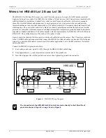
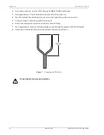
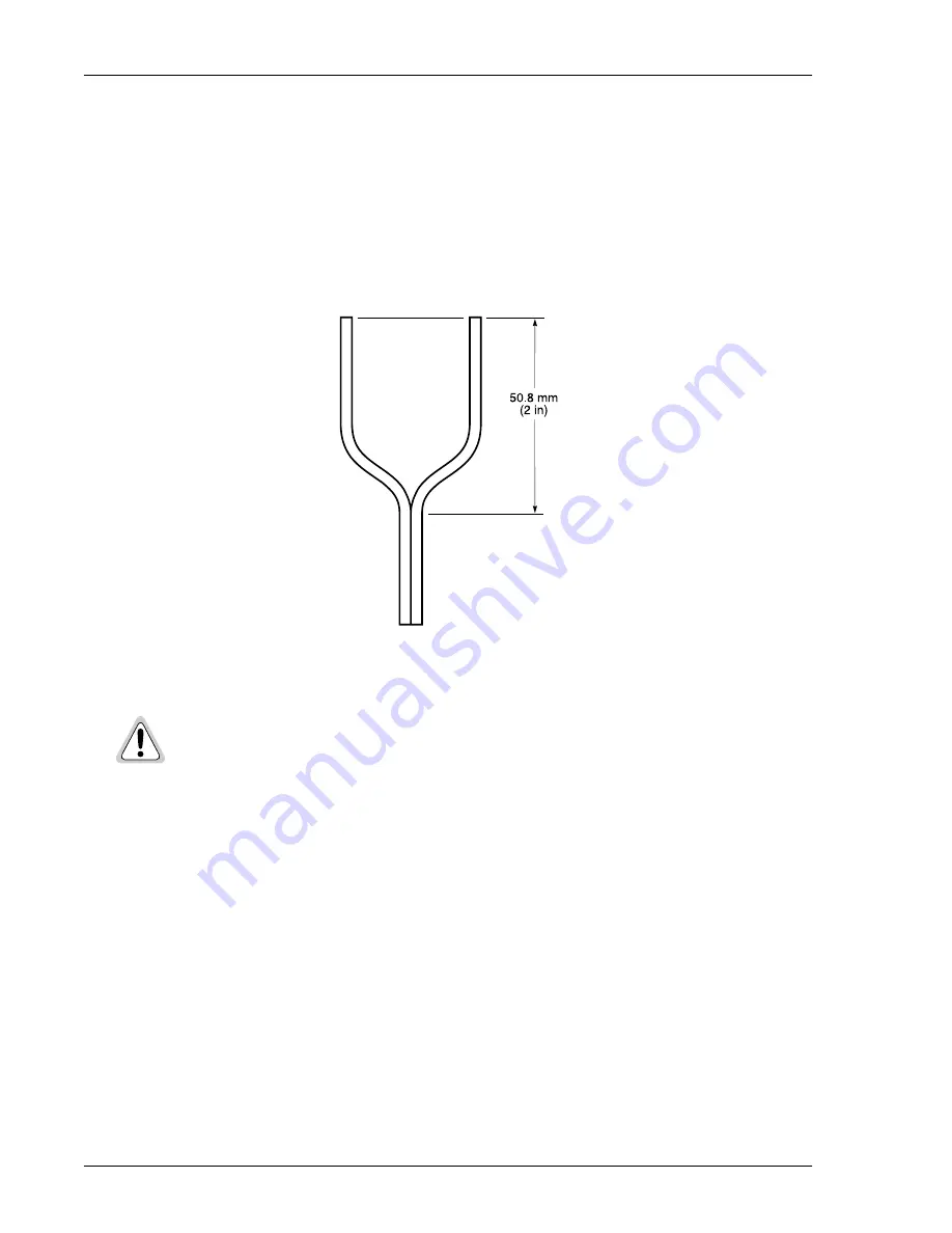
Slit the ends of the leads of each drop-wire pair and bend as shown in 

Figure 7

.

Figure 7.

Preparing the Wire Pair

Do not strip the drop-wire pair insulation.

Summary of Contents for 150-1121-22

Page 1: ...IN REMOTE ENCLOSURE ADC TELECOMMUNICATIONS INC USER MANUAL SECTION 150 450 132 02 Model List Number Part Number CLEI Code HRE 450 2B 150 1121 22 T1RHCGS4 HRE 450 3B 150 1121 32 T1M11N0C HRE 450 4B 150...

Page 2: ...of their respective companies Disclaimer of Liability Information contained in this document is company private to ADC DSL Systems Inc and shall not be modified used copied reproduced or disclosed in...

Page 3: ...equipment has been damaged in transit immediately report the extent of damage to the transportation company and to ADC Order replacement equipment if necessary Check the packing list to ensure comple...

Page 4: ...Inspecting the Shipment 150 450 132 02 Issue 2 iv March 6 2000 HRE 450List 2B List 3B List 4B...

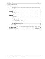
Page 5: ...____________________________________________ 5 Installation Kit 5 Locating the Necessary Tools 5 Installing the HRE 450 6 Wiring the HRE 450 List 2B and List 3B 8 Wiring the HRE 450 List 4B No Stub 9...

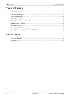
Page 6: ...2 HRE 450 Components 3 3 HRE 450 Front Cover 6 4 HRE 450 Wiring Diagram 8 5 Wiring Diagram and Barcode Label Locations 9 6 Bottom View of the HRE 450 9 7 Preparing the Wire Pair 10 8 Locating the QFC...

Page 7: ...ole It can not be installed underground as this requires a sealed or pressurized unit to prevent water intrusion The HRE 450 List 2B has a single 20 foot gel filled cable stub the HRE 450 List 3B has...

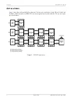
Page 8: ...4B APPLICATIONS Figure 1 shows three different HRE 450 applications The line unit is installed in a Central Office CO shelf and the HRU or HDU is housed in an HRE 450 For customer applications located...

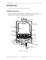
Page 9: ...lity of the HRE 450 HRE 450 COMPONENTS The HRE 450 is a weather resistant non pressurized white rectangular enclosure with a removable front lid It can house one unit with either 400 or 200 mechanics...

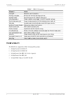
Page 10: ...both DS1 and HDSL interfaces 56 pin card edge connector Provides card edge connectivity for the installed remote or doubler unit Card guides Guides and aligns card with card edge connector during car...

Page 11: ...contact your ADC sales representative LOCATING THE NECESSARY TOOLS To install the HRE 450 you need the following tools Blade screwdriver Drill Wood metal or concrete drill bit depending on installati...

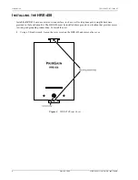
Page 12: ...r wood surface such as a wall or telephone pole using the hardware provided in the Installation Kit The HRE 450 must be installed above ground in a location that provides access to wiring and groundin...

Page 13: ...l bit to drill the mounting screw holes into the wooden surface If the installation location is concrete use a drill with a concrete drill bit that is slightly smaller than the diameter of the anchor...

Page 14: ...pheric temperatures ground chemicals and stresses expected in standard installations The cable complies with the requirements of ANSI ICEA S 85 625 1989 and REA PE 22 The outside diameter of the cable...

Page 15: ...UB Connect the HRE 450 List 4B to the signal cables and ground wire 1 Loosen the compression connector nuts on the bottom of the HRE 450 using one of the following methods Using your hand turn the com...

Page 16: ...ped wire into the ground wire access then tighten the ground wire connector 5 Using your fingers tighten the ground wire connector 6 Remove the compression connector nut from the cable stub fitting 7...

Page 17: ...7 16 inch wrench to rotate each QFCM lug 1 4 turn clockwise 12 Using your fingers do not use pliers or a wrench tighten the cable rifting compression nut If necessary use groove joint pliers to hold...

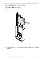
Page 18: ...the slot until firmly seated 2 Slide the enclosure s locking tab over the doubler or remote unit s handle and tighten the tab screw Figure 9 Installing a Remote or Doubler Unit in an HRE 450 3 Verify...

Page 19: ...inch 18 57 cm Depth 2 31 inch 5 87 cm Enclosure Lid Height 10 25 inch 26 cm Width 7 5 inch 19 1 cm Depth 2 69 inch 6 83 cm Quiet Front Connector Modules QFCM Electrical Protection Each QFCM module con...

Page 20: ...d Integration Testing System Turn Up and Testing Network Monitoring upstream or downstream Power Monitoring and Remote Surveillance Service Maintenance Agreements Systems Operation BIA Technical Assis...

Page 21: ...ute AWG American Wire Gauge CLEI Common Language Equipment Identifier CO Central Office CSA Carrier Service Area DS1 Digital Signal level 1 GND Ground HDSL High bit rate Digital Subscriber Line HDU Hi...

Page 22: ...Appendix C Glossary 150 450 132 02 Issue 02 16 March 6 2000 HRE 450 List 2B List 3B and List 4B...

Page 23: ...the date of purchase the media on which software is stored will be free from material defects under normal use ADC will replace defective media at no charge if it is returned to ADC during the 30 day...

Page 24: ...nklin Avenue Tustin CA 92780 7013 Tel 714 832 9922 Fax 714 832 9924 Technical Assistance Tel 800 638 0031 Tel 714 730 3222 Fax 714 730 2400 DNV Certification Inc REGISTERED FIRM ISO 9001 TL 9000 DOCUM...

Reviews: