


150-450-132-02, Issue 02
Installation
HRE-450 List 2B, List 3B, and List 4B
March 6, 2000
11
9
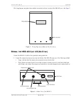
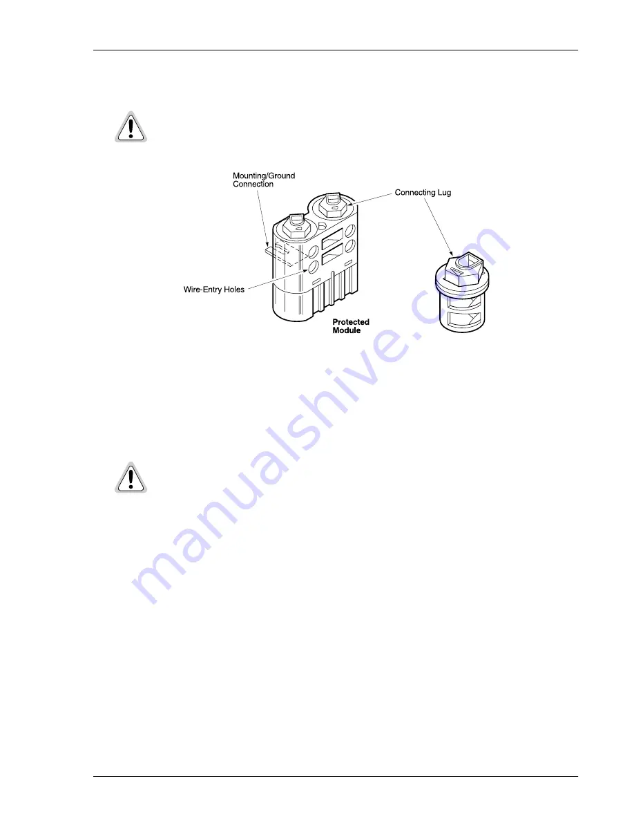
Use a Type 216C (7/16 inch) wrench to rotate each QFCM lug 1/4 turn counterclockwise to open the
connectors.
Figure 8.
Locating the QFCM Connecting Lug
10
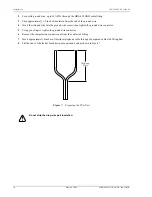
Insert the first pair’s Tip and Ring wires into the Wire-Entry holes in the first QFCM, until the wires touch
the ends of the transparent plastic caps.
11
While holding the Tip and Ring wires in place with your fingers, use a Type 216C (7/16 inch) wrench to rotate
each QFCM lug 1/4 turn clockwise.
12
Using your fingers (do not use pliers or a wrench), tighten the cable rifting compression nut.
If necessary, use groove-joint pliers to hold each cable rifting center locknut while tightening each
compression nut with your fingers.
13
Use cable ties to dress the wires that enter the enclosure box and connect to the QFCM terminals, per local
practice.
14
Position and secure the ground wire along the installation surface and connect it to a nearby ground, per local
practice.
Do not rotate the QFCM lug more than 1/4 turn or you will cut the wire.
Do not rotate the QFCM lug more than 1/4 turn or you will cut the wire.


