background image

Pin Assignments


 150-204-100-03, Issue 3

14

May 7, 1999

 HRE-204 List 1 and List 2

HLU A

LARM

 O

UTPUT

 I

NTERFACE

When HLU-431 line units are installed in the HRE-204 List 1 and List 2, the system alarm relay contacts for each 
slot, Normally Open (NO) and Common (COM), are bused together and made available on the Euro style terminal 
block TB5. 

Figure 12

 shows the TB5 pin assignments.

Figure 12.

System Alarm (TB5) Pin Assignments

F

ACILITY

 S

IDE

 HDSL C

ONNECTIONS

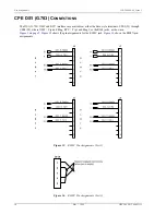
The HDSL facility side ports are available through the FAC ports of the Euro style screw-down terminal blocks. 

Figure 13

 shows the pin assignments for TB1 (Slot 1), and 

Figure 14

 shows the TB2 pin assignments (Slots 2, 3, 

and 4).

Figure 13.

TB1 Pin Assignments

1

2

22

22

22

22

30

30

30

30

ALMCOM

ALMCOM

ALMCOM

ALMCOM

ALMNO

ALMNO

ALMNO

ALMNO

TB5

S1

S2

S3

S4

DS1 T I P 1

TB1

S

L

O

T

1

T

T

T 1

CPE

FA

C

T 1

R

R

R1

R1

1
2
3
4
5
6
7
8

55
49

5

15

7

13
41
47

DS1 RI NG 1

DS1 RI NG 1

HDSL

T I P L 1

HDSL

RI NG L 1

HDSL

T I P L 2

HDSL

RI NG L 2

DS1

T I P 1

Summary of Contents for 150-204-100-03

Page 1: ...HiGain HiGain USER MANUAL HRE 204 List 1 and List 2 HiGain Remote Enclosure Product Catalog 150 204 100 03 CLEI T1MF5004 T1MF6004 ...

Page 2: ... trademarks of their respective companies Disclaimer of Liability Information contained in this document is company private to ADC DSL Systems Inc and shall not be modified used copied reproduced or disclosed in whole or in part without the written consent of ADC Contents herein are current as of the date of publication ADC reserves the right to change the contents without prior notice In no event...

Page 3: ...nt equipment if necessary Check the packing list to ensure complete and accurate shipment of each listed item If the shipment is short or irregular contact ADC DSL Systems Inc as described in Product Support on page 19 If you must store the equipment for a prolonged period store the equipment in its original container Notes contain information about special circumstances Cautions indicate the poss...

Page 4: ...Inspecting Shipment 150 204 100 03 Issue 3 iv May 7 1999 HRE 204 List 1and List 2 ...

Page 5: ..._______________________________________________ 9 48 Volt Power Options 9 Pin Assignments _____________________________________________________________________ 11 Slot Pin Assignments 11 HLU Alarm Output Interface 14 Facility Side HDSL Connections 14 CPE DS1 G 703 Connections 16 Appendix A Specifications____________________________________________________________ 17 Appendix B Abbreviations ______...

Page 6: ...ge 8 Figure 8 TB3 and TB4 Pin Assignments 10 Figure 9 HRU Pin Assignments All Lists 11 Figure 10 HLU 431 Pin Assignments 12 Figure 11 ERU 412 Pin Assignments 13 Figure 12 System Alarm TB5 Pin Assignments 14 Figure 13 TB1 Pin Assignments 14 Figure 14 TB2 Pin Assignments 15 Figure 15 RJ48C Pin Assignments List 1 16 Figure 16 RJ48X Pin Assignments List 2 16 Figure 17 Bar Code and Configuration Number...

Page 7: ...rcuit backplane provides terminal block or RJ48 connectors tamper proof locking screw for security accepts 48 V input power for HLU applications wall or desktop mounting separate 48 V input terminals for slot isolation optional wall hinge mount pre painted cold rolled 16 gauge steel construction APPLICATIONS HiGain provides a quick and cost effective way of delivering T1 High Capacity Digital Serv...

Page 8: ...1999 HRE 204 List 1 and List 2 BACKPLANE Figure 1 shows the HRE 204 List 1 and List 2 backplane Table 1 on page 3 describes its connectors Figure 1 HRE 204 List 1 and List 2 Backplane TB2 RJ48 jacks J3 J4 J2 J1 TB1 TB3 TB4 TB5 G1 J5 J6 J7 J8 ...

Page 9: ...E jacks List 1 or RJ48X jacks List 2 TB1 Terminal block connector for Slot 1 CPE DS1 and FAC HDSL interfaces TB2 Terminal block connector for Slots 2 3 and 4 CPE and FAC interfaces TB3 Terminal block connector for providing 48VA and GND A power connections to Slots 1 and 2 TB4 Terminal block connector for providing 48VB and GND B power connections to Slots 3 and 4 TB5 Terminal block connector for ...

Page 10: ...ur slot connectors J1 through J4 These slots are for installing HiGain Line Units and HiGain Remote Units Figure 3 HRE 204 List 1 and List 2 Remote Enclosure INSTALLATION This section provides information on installing and mounting the HRE 204 List 1 and List 2 List 1 and List 2 INSTALLATION KIT two mounting screws two anchor nuts ...

Page 11: ...l Mounting To mount the enclosure on a wall loosen the backplate and use it as a template for the two mounting holes as follows 1 Loosen the 216 HEX security nut on the side panel Figure 4 with a 7 16 inch CAN wrench Figure 4 Side Panel Assembly 2 Remove the side panel 3 Remove the top retaining screw that holds the backplate to the chassis Regardless of where the HRE 204 List 1 and List 2 is moun...

Page 12: ... clasps and unlatch it from the enclosure 5 Use the backplate as a template to mark the wall locations for drilling the mounting holes Figure 5 Figure 5 HRE 204 List 1 and List 2 List 1 Backplate 6 Drill pilot holes and attach the backplate to the backboard with the two No 10 x 5 8 inch sheet metal screws and washers supplied with the remote enclosure ...

Page 13: ...nd Hinging View 8 Reattach the side panel and tighten the 216 HEX security nut to secure it to the main chassis When the main chassis is attached to the backplate it can be rotated down to provide access to the backplane connector and other internal areas Unlatch the chassis from the two friction clasps in the upper corner of the backplate to lower it See Figure 6 for hinging details ...

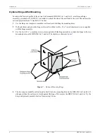
Page 14: ...unting holes 2 Drill pilot holes and attach the hinge to the wall with the two No 10 x 5 8 inch sheet metal screws supplied with the hinge assembly 3 Use the two 6 32 x 1 4 machine screws also supplied with the hinge assembly to attach the hinge to the two mounting holes on the HRE 204 List 1 and List 2 backplate as shown in Figure 7 Figure 7 Optional Mounting Hinge 4 The two snap in standoffs on ...

Page 15: ...e s GR 1089 DEC 1996 48 VOLT POWER OPTIONS When using the HRE 204 List 1 and List 2 to locally power HRU plugs or HLU 431 line units the 48 V power can be provided in either an isolated or non isolated mode Power is provided to terminal blocks TB3 and TB4 the pin assignments for which are shown in Figure 8 on page 10 The isolated mode requires two separate external power supplies which are connect...

Page 16: ...used to provide 48 V power for various plug applications as shown in Table 2 Minimum input power lead wire size current capacity is based on 1000 circular mils per ampere Table 2 Power Requirements for Various Plug Applications HiGain Unit Maximum power per unit Number of units Power Required mA Power supply Input Power AWG Wire Size Two Inputs One Input HRU 402 3 5 Watts 1 73 Westell 6048 01 100 ...

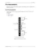
Page 17: ...ector pin assignments of the HiGain plugs which are compatible with the HRE 204 List 1 and List 2 SLOT PIN ASSIGNMENTS Slot pin assignments for the various plugs compatible with the HRE 204 List 1 and List 2 are shown in the following figures Figure 9 Figure 10 on page 12 Figure 11 on page 13 Figure 9 HRU Pin Assignments All Lists ...

Page 18: ...Pin Assignments 150 204 100 03 Issue 3 12 May 7 1999 HRE 204 List 1 and List 2 Figure 10 HLU 431 Pin Assignments ...

Page 19: ... Figure 11 ERU 412 Pin Assignments If you are installing HiGain ETSI remote units in the HRE 204 List 1 and List 2 use only the 1209 G 703 ERU The 75 9 G 703 ERU should not be used The 75 9 interface requires BNC connectors that are not available in the HRE 204 List 1 and List 2 ...

Page 20: ...rm TB5 Pin Assignments FACILITY SIDE HDSL CONNECTIONS The HDSL facility side ports are available through the FAC ports of the Euro style screw down terminal blocks Figure 13 shows the pin assignments for TB1 Slot 1 and Figure 14 shows the TB2 pin assignments Slots 2 3 and 4 Figure 13 TB1 Pin Assignments 1 2 22 22 22 22 30 30 30 30 ALMCOM ALMCOM ALMCOM ALMCOM ALMNO ALMNO ALMNO ALMNO TB5 S1 S2 S3 S4...

Page 21: ...ate the appropriate connector see the pin assignment representations in Slot Pin Assignments on page 11 If the Loop 1 and Loop 2 leads are reversed a CHREV Channels Reversed message is displayed in the ALARMS display field when viewing the HiGain Status screen This condition does not affect system operation but should be corrected to avoid any confusion regarding the identities of the two HDSL loo...

Page 22: ...es are available at either the Euro style terminals CPE1 J5 through CPE4 J8 where XMT Tip and Ring RCV Tip1 and Ring1 or the RJ48 jacks as shown in Figure 1 on page 2 Figure 15 shows the pin assignments for the RJ48C jack Figure 16 shows the RJ48X pin assignments Figure 15 RJ48C Pin Assignments List 1 Figure 16 RJ48X Pin Assignments List 2 ...

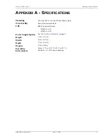
Page 23: ...two type 400 mechanics plugs Telco Facility Euro style terminal blocks CPE RJ48 Connector Options RJ48C List 1 RJ48X List 2 Power Supply Option See 48 Volt Power Options on page 9 Height 5 8 in 15 cm Width 4 8 in 12 cm Depth 7 5 in 19 cm Weight 3 0 lb 1 4 kg Operating Environment Temp 0 F to 158 F 18 C to 70 C Humidity 0 to 95 non condensing ...

Page 24: ... CLEI Common Language Equipment Identifier CO Central Office CP Customer Premises ECI Equipment Catalog Item EDU HiGain E1 Doubler Unit EMI ElectroMagnetic Interference ETSI European Telecommunications Standards Institute HCS HiGain Card Shelf HDU HiGain T1 Doubler Unit HRE HiGain Remote Enclosure ICEA Insulated Cable Engineers Association LED Light Emitting Diode REA Rural Electrification Adminis...

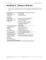
Page 25: ...ting System Turn Up and Testing Network Monitoring upstream or downstream Power Monitoring and Remote Surveillance Service Maintenance Agreements Systems Operation ADC Technical Assistance Center 800 366 3891 ext 73223 800 638 0031 714 730 3222 Fax 714 730 2400 Email wsd_support adc com Technical Information System Network Configuration Product Specification and Application Training product specif...

Page 26: ...description of the information on the labels Figure 17 Bar Code and Configuration Number Label Locations Table 3 Bar Code and Configuration Number Label Descriptions Item Description CLEI code label Contains the human readable Common Language Equipment Identifier CLEI code number and Equipment Catalog Item ECI bar code number Bar code and configuration number label This label contains the configur...

Page 27: ...150 204 100 03 Issue 3 Appendix C Product Support HRE 204 List 1 and List 2 May 7 1999 21 ...

Page 28: ...ransportation charges for shipment of replacement products to Buyer unless no trouble is found NTF in which case the Buyer will pay transportation charges ADC may use reconditioned parts for such repair or replacement This warranty does not apply to any product which has been repaired worked upon or altered by persons not authorized by ADC or in ADC s sole judgment has subjected to misuse accident...

Page 29: ...n Avenue Tustin CA 92780 7013 Tel 714 832 9922 Fax 714 832 9924 Technical Assistance Tel 800 638 0031 Tel 714 730 3222 Fax 714 730 2400 DNV Certification Inc REGISTERED FIRM ISO 9001 TL 9000 DOCUMENT 150 204 100 03 ISSUE 3 3P 8 1219488 ...

Reviews: