Appendix A - Technical Reference
150-504-100-03
32
August 1, 2002
HRE-504 List 1, List 1B, and List 2
M
AINTENANCE
P
ROCEDURES
This section covers maintenance procedures for the HRE-504.
Splicing
Splicing consists of connecting the wire pairs of the HRE-504 cable stub to the main cable located in the splice
case. The following sections contain step-by-step procedures for:
•
Preparing the stubs for splicing into the main cable, as described in
below.
•
Splicing the stubs into the main cable, as described in
“Splicing Procedure” on page 34
.
•
Dressing and taping the final splice in the splice case, as described in
“Post-splicing Procedure” on page 35
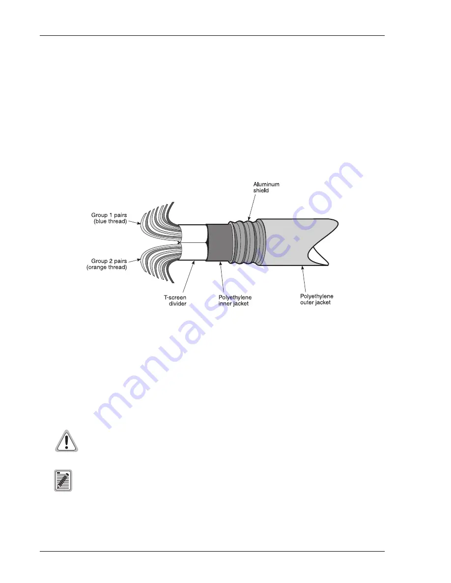
Figure 14.
Cable Stub Construction
When using these splicing procedures, maintain cable pair integrity when splicing stub pairs into the main cable.
Follow local practices as required.
Pre-splicing Procedure
To pre-splice the enclosure cable stub, perform the following steps:
1
Strip a sufficient length of outer jacket, aluminum shield, and mylar sheath from the cable stub.
2
Strip the main cable as required by the cable manufacturer.
3
Install shield bonding connectors in accordance with standard practices.
Ground the HRE-504 enclosure before splicing the cable stubs into the main cable. The
grounding method discussed in
“Grounding the Enclosure” on page 12
or an accepted local
grounding method must be in effect at all times to safeguard personnel.
The HRE-504 comes with a screened cable stub that is precut and capped.
The cable butt is considered to be the end of the cable stub most distant from the enclosure.
Summary of Contents for 150-2202-01
Page 4: ...Inspecting the Shipment 150 504 100 03 iv August 1 2002 HRE 504 List 1 List 1B and List 2...
Page 8: ...List of Tables 150 504 100 03 viii Augusr 1 2002 HRE 504 List 1 List 1B and List 2...
Page 53: ...Appendix D Abbreviations 150 504 100 03 46 August 1 2002 HRE 504 List 1 List 1B and List 2...


