background image

44

American Dryer Corp.

113329 - 14

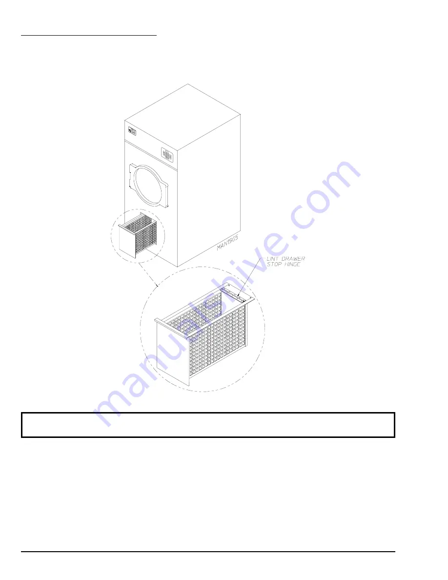
D.  LINT DRAWER REMOVAL

To remove the lint drawer from the dryer pull drawer out approximately halfway.  Rotate/move lint drawer stop
hinge (refer to the illustration below) downward and pull the drawer out.

IMPORTANT: After replacing the lint drawer back into the dryer, be sure to rotate/move hinge back

to the upward stop position.

Summary of Contents for AD-25V

Page 1: ...Appelez immédiatement votre fournisseur de gaz depuis un voisin Suivez les instructions du fournisseur Si vous ne pouvez rejoindre le fournisseur de gaz appelez le service des incendies L installation et l entretien doivent être assurés par un installateur ou un service d entretien qualifié ou par le fournisseur de gaz WARNING FIRE OR EXPLOSION HAZARD Failure to follow safety warnings exactly coul...

Page 2: ...ocessed accurately and promptly These instructions are only valid if the following country code is on the appliance If this code is not present on the appliance it is necessary to refer to the technical instructions which will provide the necessary information concerning the modification of the appliance to the condition of use for the country In accordance with EN ISO 3166 1 the names of countrie...

Page 3: ...rancher Des erreurs de câblage peuvent entraîner un fonctionnement inadéquat WARNING Children should not be allowed to play on or near the dryer s Children should be supervised if near dryer s in operation Under no circumstances should the dryer door switch lint drawer switch or the heat safety circuit devices ever be disabled DO NOT MODIFY THIS APPLIANCE The dryer must never be operated with any ...

Page 4: ... should be accepted but the number received and the number refused must be noted on the receipt 4 If you determine that the dryer was damaged after the trucker has left your location you should call the delivering carrier s freight terminal immediately and file a claim The freight company considers this concealed damage This type of freight claim is very difficult to get paid and becomes extremely...

Page 5: ...ier from a neighbor s phone Follow the gas supplier s instructions f If you cannot reach your gas supplier call the fire department 5 Installation and service must be performed by a qualified installer service agency or gas supplier 6 Dryer s must be exhausted to the outdoors 7 Although ADC produces a very versatile dryer there are some articles that due to fabric composition or cleaning method sh...

Page 6: ...leaning solvents or fumes 13 Remove articles from the dryer as soon as the drying cycle has been completed WARNING Articles left in the dryer after the drying and cooling cycles have been completed can create a fire hazard 14 READ AND FOLLOW ALL CAUTION AND DIRECTION LABELS ATTACHED TO THE DRYER 15 For safety proper operation and optimum performance the dryer must not be operated with a load less ...

Page 7: ...8 20 32 cm COMPRESSED AIR CONNECTION N A COMPRESSED AIR VOLUME N A OVEN SIZE kW Btu hr kcal hr 15 51 200 12 900 18 61 400 15 400 20 68 200 17 200 24 81 900 20 600 30 102 300 25 700 VOLTAGE AVAILABLE 120 480V 1 3ø 2 3 4w 50 60 Hz APPROXIMATE NET WEIGHT 435 lb 197 3 kg APPROXIMATE SHIPPING WEIGHT 474 lb 214 8 kg AIRFLOW 60 Hz 460 cfm 13 cmm 50 Hz 383 cfm 10 85 cmm STEAM CONSUMPTION 98 8 lb hr 44 8 k...

Page 8: ...8 American Dryer Corp 113329 14 SPECIFICATIONS NOTE ADC reserves the right to make changes in specifications at any time without notice or obligation ...

Page 9: ...tion of the dryer The dryer can be moved to its final location while still attached to the skid or with the skid removed To unskid the dryer locate and remove the four 4 bolts securing the base of the dryer to the wooden skid Two 2 are at the rear base remove the back panel for access and two 2 are located in the bottom of the lint chamber To remove the two 2 bolts located in the lint chamber area...

Page 10: ...nce provisions must be made from combustible construction as noted in this manual refer to Dryer Enclosure Requirements in Section C 6 Provisions must be made for adequate clearances for servicing and for operation as noted in this manual refer to Dryer Enclosure Requirements in Section C 7 Dryer must be exhausted to the outdoors as noted in this manual refer to Exhaust Requirements in Section E 8...

Page 11: ...um 24 inches 60 96 cm is suggested for ease of maintenance 1 inch 2 54 cm maximum for electric dryers 18 inch 45 72 cm minimum for steam dryers NOTE Air considerations are important for proper and efficient operation Dryers may be positioned sidewall to sidewall However a 1 16 1 5875 mm minimum allowance must be made for the opening and closing of the control door It is suggested that the dryer be...

Page 12: ...le However they must be set up in such a manner that the make up air is distributed equally to the dryers The dryer must be installed with provisions for adequate combustion and make up air supply EXAMPLE For a bank of eight 8 dryers two 2 unrestricted openings measuring 2 feet by 2 feet 0 61 meters by 0 61 meters 4 square feet 0 372 square meters are acceptable IMPORTANT Make up air openings shou...

Page 13: ... should overlap the duct to which it is connected ALL ductwork joints must be taped to prevent moisture and lint from escaping into the building Additionally inspection doors should be installed at strategic points in the exhaust ductwork for periodic inspection and cleaning IMPORTANT When connecting ductwork to the dryer exhaust duct be sure that when screws are used they DO NOT restrict the oper...

Page 14: ...ches 25 4 cm must be used HORIZONTAL VENTING When a single 8 inch 20 32 cm horizontal vent is used the ductwork to the outlet cannot exceed 25 feet 7 62 meters refer to Illus A below This calculation of 25 feet 7 62 meters compensates or allows for the use of a maximum of only one 1 elbow which is the outside outlet protection Illus A ...

Page 15: ...a of the ductwork can only be increased to an extent For extended ductwork runs a professional HVAC firm must be consulted for proper venting information VERTICAL VENTING When vertical single 10 inch 25 4 cm venting is used refer to Illus B below the ductwork from the dryer to the outside outlet cannot exceed 40 feet 12 19 meters refer to Illus B below This calculation compensates for the use of a...

Page 16: ...ryers maximum should be connected to one 1 main common duct with a vertical run NOTE Distance between dryer single ducts being connected to the main common duct must be a minimum of 34 1 4 87 cm dryer width Ductwork should be laid out in such a manner where allowances are made at rear area of the dryer for removal of rear service panels or guards The illustrations on page 17 show the minimum cross...

Page 17: ...113329 14 www adclaundry com 17 HORIZONTAL VENTING Illus C VERTICAL VENTING Illus D ...

Page 18: ...RTANT Each circuit must be connected to an independently protected branch circuit IMPORTANT USE ONLY COPPER CONDUCTOR CABLE of proper ampacity and insulation in accordance with electric codes for making service connections NOTE The use of aluminum wire will VOID THE WARRANTY IMPORTANT A separate circuit servicing each dryer must be provided 2 Electrical Service Specifications a Electric Service 1 ...

Page 19: ...ction may be to a proven earth ground at the location service panel For added personal safety when possible it is suggested that a separate ground wire no 18 minimum be connected from the ground connection of the dryer to a grounded cold water pipe DO NOT ground to a gas pipe or hot water pipe The grounded cold water pipe must have metal to metal connection ALL the way to the electrical ground If ...

Page 20: ...L listed power cord or pigtail wire size must conform to rating of dryer or the dryer can be hard wired directly to the service breaker panel In both cases a strain relief must be installed where the wiring enters the dryer SINGLE PHASE 1Ø ELECTRICAL CONNECTIONS LEADS Black White White Neutral Green Ground or L2 ...

Page 21: ...at the rear upper left corner of the dryer The ground connection is made to the copper lug also provided in this box To gain access to the service box and contactor the service box cover must be removed Providing local codes permit power to a gas dryer or steam dryer can be made by the use of a flexible UL listed power cord or pigtail wire size must conform to rating of dryer or the dryer can be h...

Page 22: ...TION The dryer must be grounded A ground lug has been provided for this purpose IMPORTANT A CIRCUIT SERVICING EACH DRYER MUST BE PROVIDED The only electrical connections to the dryer are the 3 phase 3ø leads L1 L2 L3 and sometimes Neutral and ground Single phase 1ø power for the control circuit is done by the factory at the contactor relay and no other wiring connections are ...

Page 23: ...ECIFICATIONS IMPORTANT NOTES A B C 208 VAC AND 230 240 VAC ARE NOT THE SAME When ordering specify exact voltage When fuses are used they must be dual element time delay current limiting class RK1 or RK5 ONLY Calculate determine correct fuse value by applying either local and or National Electrical Codes to listed appliance amp draw data Circuit breakers are thermal magnetic industrial motor curve ...

Page 24: ... WARRANTY WARNING FIRE OR EXPLOSION COULD RESULT 1 Gas Supply The gas dryer installation must meet the American National Standard National Fuel Gas Code ANSI Z223 1 LATEST EDITION or in Canada the Canadian Installation Codes CAN CGA B149 1 M91 Natural Gas or CAN CGA B149 2 M91 Propane Gas or LATEST EDITION as well as local codes and ordinances and must be done by a qualified professional NOTE Unde...

Page 25: ...input per dryer 78 000 BTU hr 19 656 kcal hr 1 Natural Gas Regulation is controlled by the dryer s gas valve s internal regulator Incoming supply pressure must be consistent between a minimum of 6 0 in WC 19 92 mb and a maximum of 12 0 in WC 29 9 mb pressure 2 Propane Gas Dryers made for use with propane gas have the gas valve s internal pressure regulator blocked open so that the gas pressure mus...

Page 26: ... the appliance BTUs being supplied Installer within Australia refer to AS NZS5601 1 for guidance on gas supply pipe sizing required for this appliance installation The dryer is provided with a 1 2 N P T inlet pipe connection extending out the back area of the burner box The minimum pipe size supply line to the dryer is 1 2 N P T For ease in servicing the gas supply line of each dryer must have its...

Page 27: ...at resist the action of natural gas and propane gas must be used IMPORTANT Test ALL connections for leaks by brushing on a soapy water solution liquid detergent works well WARNING NEVER TEST FOR LEAKS WITH A FLAME ALL components materials must conform to National Fuel Gas Code Specifications ANSI Z223 1 LATEST EDITION or in Canada CAN CGA B149 1 M91 Natural Gas or CAN CGA B149 2 M91 Propane Gas or...

Page 28: ...valve with a proper trap and dirt pocket IMPORTANT Failure to comply with the requirements stipulated in this manual can result in component failure which will VOID THE WARRANTY NOTE The dryer is manufactured with a pneumatic piston damper system which requires an external supply of air 80 PSI 10 PSI 5 51 bar 0 68 bar 1 Steam Coil pH Level The normal pH level for copper type steam coils must be ma...

Page 29: ...l allow the dryer to be isolated from the supply main and the return main if the dryer needs maintenance work e Install an inverted bucket steam trap and check valve at least 12 inches 30 48 cm below the steam coil as close to the coil as possible 1 A trap with a capacity of 350 lb 160 kg of condensate per hour at 125 PSI 8 61 bar is needed for each unit f The supply line and the return line shoul...

Page 30: ...ea of the dryer just in front of the electric service relay box a Air Requirements There is no air requirement for dryers with the Electromechanical Steam Damper Option Shaded areas are stated in metric equivalents b Air Connection Air connection to system 1 8 N P T c Air Regulation No air regulator or filtration is provided with the dryer External regulation filtration of 80 PSI 5 51 bar must be ...

Page 31: ...t coil providing instant heat to start the drying process When the damper is closed ambient air is drawn directly into the tumbler allowing a rapid cool down Diagram 1 shows the damper in the heating open mode allowing heat into the tumbler Diagram 2 shows the damper in the cool down closed mode pulling ambient air directly into the tumbler without passing through the coils NOTE With the dryer off...

Page 32: ...mper Air Piston Flow Control Operation Adjustment Damper operation was tested and adjusted prior to shipping at 80 PSI 5 51 bar If damper air adjustment is necessary locate the flow control valve and make the necessary adjustments as noted below ...

Page 33: ...h adjustment must be checked to assure that this important safety control is functioning 5 Check bolts nuts screws terminals and fittings for tightness and security 6 GAS MODELS be sure that ALL gas shutoff valves are in the open position 7 Check ALL back guard panels and service box covers have been replaced 8 Check the lint drawer to assure that it is closed and secured in place 9 Rotate the tum...

Page 34: ...el dryers are equipped with an ignition system which has internal diagnostics If ignition is not established after one 1 time the heat circuit in the ignition module will attempt two 2 more ignitions total of three 3 ignition attempts If there is no flame after the third ignition attempt the module will lockout until it is manually reset To reset the ignition system open and close the main door an...

Page 35: ...ont the blower squirrel cage fan should spin in the clockwise CW direction If it is the phasing is correct If the phasing is incorrect reverse two 2 of the three 3 leads at connections L1 L2 and L3 of the power supply to the dryer IMPORTANT If the blower squirrel cage fan is rotating in the wrong direction this will not only drastically reduce drying efficiency but it can also cause premature comp...

Page 36: ... and the L E D display will read the temperature cycle selected and the drying time d The dryer will continue through the drying and cooling cycles showing time counting downward IMPORTANT If the door is opened during a cycle both the heat and motor will stop However the microprocessor controller computer will continue to count downward in time Continuation of the cycle will resume only after the ...

Page 37: ...will sound for 5 seconds and the L E D display will read donE at which time the dryer will shut off NOTES 1 If the Anti Wrinkle program is active the L E D display will continue to read donE and the microprocessor controller computer will proceed through the Anti Wrinkle program until the maximum Active Guard Time has expired or until the door is opened whichever comes first The L E D display will...

Page 38: ...ryer open the main door L SHUTDOWN INSTRUCTIONS If the dryer is to be shutdown taken out of service for a period of time the following must be performed 1 Discontinue power to the dryer either at the external disconnect switch or the circuit breaker 2 Discontinue the heat supply a GAS MODELS discontinue the gas supply 1 SHUT OFF external gas supply shutoff valve 2 SHUT OFF internal gas supply shut...

Page 39: ...mber and serial number so that your inquiry is handled in an expeditious manner B PARTS 1 Replacement parts should be purchased from the reseller from whom the ADC equipment was purchased If the reseller cannot be contacted or is unknown contact the ADC Parts Department for a reseller in your area Parts may also be purchased directly from the factory by calling the ADC Parts Department at 1 269 92...

Page 40: ...s contact the ADC reseller from whom you purchased the equipment and request a dryer warranty form If the reseller cannot be contacted or is unknown warranty information can be obtained from the factory by contacting the ADC Warranty Department at 1 269 923 3000 NOTE Whenever contacting the ADC factory for warranty information be sure to have the dryer s model number and serial number available so...

Page 41: ...t damaged in transit Damage claims are the responsibility of the shipper IMPORTANT No replacements credits or refunds will be issued for merchandise damaged in transit 5 ALL returns should be shipped to the ADC factory in such a manner that they are insured and a proof of delivery can be obtained by the sender 6 Shipping charges are not the responsibility of ADC ALL returns should be prepaid to th...

Page 42: ...ABLE VAPORS AND LIQUIDS NOTE Suggested time intervals shown are for average usage which is considered six 6 to eight 8 operational running hours per day IMPORTANT Dryer produces combustible lint and must be exhausted to the outdoors Every 6 months inspect the exhaust ducting and remove any lint build up SUGGESTED CLEANING SCHEDULE EVERY THIRD OR FOURTH LOAD Clean the lint screen every third or fou...

Page 43: ...USTMENTS 7 DAYS AFTER INSTALLATION AND EVERY 6 MONTHS THEREAFTER Inspect bolts nuts screws bearing setscrews grounding connections and nonpermanent gas connections unions shutoff valves and orifices Motor and drive belts should be examined Cracked or seriously frayed belts should be replaced Tighten loose V belts when necessary Complete operational check of controls and valves Complete operational...

Page 44: ...er from the dryer pull drawer out approximately halfway Rotate move lint drawer stop hinge refer to the illustration below downward and pull the drawer out IMPORTANT After replacing the lint drawer back into the dryer be sure to rotate move hinge back to the upward stop position ...

Page 45: ...PORTANT When replacing blown fuses the replacement must be of the exact rating as the fuse being replaced WARNING ALL SERVICE AND TROUBLESHOOTING SHOULD BE PERFORMED BY A QUALIFIED PROFESSIONAL OR SERVICE AGENCY WARNING WHILE MAKING REPAIRS OBSERVE ALL SAFETY PRECAUTIONS DISPLAYED ON THE DRYER OR SPECIFIED IN THIS MANUAL MICROPROCESSOR CONTROLLER COMPUTER MODELS A No L E D display 1 Service panel ...

Page 46: ...lor fan blower G Both drive motor and blower motor are not operating DO NOT start microprocessor controller computer motor indicator dots are on 1 Fault in main door switch circuit 2 Blown fuse 2 Amp very fast acting fuse if applicable 3 Failed arc suppressor A S board for Reversing Models Only 4 Failed microprocessor controller computer 5 Failed 24 VAC transformer H Both drive motor and blower mo...

Page 47: ...er wait 1 minute and reestablish power to dryer If problem is still evident a Failed microprocessor controller computer b Failed keypad label assembly N Dryer stops during a cycle and the L E D display returns to FILL 1 Fault in microprocessor heat sensor circuit a Loose connection in wires between temperature sensor and microprocessor controller computer 2 Loose connection somewhere in main power...

Page 48: ...t protector thermostat 2 Failed microprocessor controller computer 3 No external compressed air to steam damper 80 PSI 5 51 bar is required 4 Failed steam damper 24 VAC pneumatic solenoid switch 5 Failed piston 6 Steam damper stuck closed Q Dryer operates but is taking too long to dry 1 Exhaust ductwork run is too long or is undersized back pressure must be no less than 0 and cannot exceed 0 3 in ...

Page 49: ...ertical and lateral alignment b Check gap between front panel and tumbler setscrews may have come loose and tumbler walked forward or backwards 3 Loose tumbler tie rod 4 Failed tumbler support T Excessive noise and or vibration 1 Dryer is not leveled properly 2 Impellor fan blower is out of balance a Excessive lint build up on impellor fan blower b Failed impellor fan blower 3 Loose tumbler tie ro...

Page 50: ...l cage fan motor D Both drive motor and blower motor are not operating indicator light is on 1 Fault with L1 termination at reversing timer for Reversing Models Only 2 Failed drying timer E Reversing drive motor operates in one 1 direction only stops and restarts in same direction for Reversing Models Only 1 Failed reversing contactor relay 2 Failed reversing timer F Heating unit is not operating ...

Page 51: ... taking too long to dry load 1 Heating unit cycling on hi limit thermostat for ELECTRIC MODELS ONLY 2 Steam damper binding in partially open position for STEAM MODELS ONLY 3 Lint and or dust accumulation on steam coil fins for STEAM MODELS ONLY 4 Housekeeping a Lint screen and lint compartment are not being cleaned on a regular basis b Lint accumulation in location exhaust system 5 Insufficient ma...

Page 52: ...__________________________________________________________________________________________________________________________ _________________________________________________________________________________________________________________________________ _________________________________________________________________________________________________________________________________ _________________...

Page 53: ...ER This describes the style of dryer and type of heat gas electric or steam 2 SERIAL NUMBER Allows the manufacturer to gather information on your particular dryer 3 TYPE OF HEAT This describes the type of heat for your particular dryer gas either natural gas or propane gas electric or steam 4 HEAT INPUT For Gas Dryers This describes the heat input in British thermal units per hour Btu hr or kilowa...

Page 54: ...the upper rear area of the dryer Both the dwell stop time and tumbler spin time are adjustable by mode selection switches located on the electronic timer as noted in the illustration below TIMING LEGEND SPIN TIME Adjustment Position Number Counterclockwise Clockwise Time in Seconds 30 150 DWELL STOP TIME Adjustment Position Number Counterclockwise Clockwise Time in Seconds 5 10 Values shown are 1 ...

Page 55: ...ocessor controller computer board reestablish power to the dryer b Start the drying cycle c Verify that the motor s and the heat indicator dots in the microprocessor controller computer L E D display are on Refer to the illustration below d Verify that the motor s heat and door indicator lights on the back side of the microprocessor controller computer board are lit Refer to the illustration below...

Page 56: ...ion Start the drying cycle When the gas burner ignites within the chosen trial for ignition time 6 seconds the flame sensor detects gas burner flame and signals the DSI module to keep the gas valve open as long as there is a call for heat The DSI module will LOCKOUT if the gas burner flame is not sensed at the end of the trial for ignition period The trial for ignition period will be repeated for ...

Page 57: ...burner flame should now be established e With the burner flame on remove the flame sensor wire from the FS terminal of the DSI module f The burner flame must shut off and the ignition module must lockout with the DSI module s indicator light red g Stop the drying cycle with the flame sensor wire still removed restart the drying cycle h The ignition module must proceed through the prepurge with the...

Page 58: ...uring the cycle the dryer will not recognize the open state of the burner hi limit thermostat and will start or continue through the drying cycle with no heat Manual reset hi limit thermostat must be reset manually This hi temperature condition may be caused due to a restricted exhaust poor airflow or improper burner oven operation The location of the manual reset hi limit switch is on the right s...

Page 59: ...ate of the hi limit thermostat and will start or continue through the drying cycle with no heat Manual reset hi limit must be reset manually This hi temperature condition may be caused due to a restricted exhaust poor airflow or improper heating unit operation The location of the manual reset hi limit is in the lint chamber area WARNING Discontinue power to dryer before attempting to reset hi limi...

Page 60: ...ADC Part No 113329 14 06 09 22 ...

Reviews: