background image

12

American Dryer Corp.

112174-7

Electrical Information ________________

Electrical Requirements

All electrical connections must be made by a properly licensed
and competent electrician.  This is to ensure that the electrical
installation is adequate and conforms to local and state
regulations or codes.  In the absence of such codes, all
electrical connections, materials, and workmanship must
conform to the applicable requirements of the National
Electrical Code ANSI/NFPA NO. 70-LATEST EDITION or in
Canada, the Canadian Electrical Codes Parts 1 & 2 CSA
C22.1-1990 or LATEST EDITION.

IMPORTANT:

 Failure to comply with these codes or

ordinances, and/or the requirements stipulated in this
manual can result in personal injury or component failure.

NOTE: 

Component failure due to improper installation will

void the warranty.

Each pocket should be connected to an independently
protected branch circuit.  The dryer must be connected with
copper wire only.  Do not use aluminum wire, which could
cause a fire hazard.  The copper conductor wire/cable must
be of proper ampacity and insulation in accordance with
electric codes for making all service connections.

NOTE: 

The use of aluminum wire will void the warranty.

IMPORTANT: 

A separate protected circuit must be

provided to each pocket.

NOTE: 

An individual ground circuit must be provided to

each dryer, do not daisy chain.

IMPORTANT: 

The dryer must be connected to the electric

supply shown on the data label.  In the case of 208 VAC or
240 VAC, the supply voltage must match the electric
service specifications of the data label exactly.

The wire size must be properly sized to handle the related
current.

!

 WARNING

208 VAC and 240 VAC are not the same.  Any damage
done to dryer components due to improper voltage
connections will automatically void the warranty.

NOTE: 

Component failure due to improper voltage

application will void the warranty.

The manufacturer reserves the right to make changes in
specifications at any time without notice or obligation.

Check your national and local code for breaker and wire size

8/18/14

Grounding

A ground (earth) connection must be provided and installed
in accordance with state and local codes.  In the absence of
these codes, grounding must conform to applicable
requirements of the National Electrical Code ANSI/NFPA NO.
70-LATEST EDITION, or in Canada, the installation must
conform to applicable Canada Standards: Canadian Electrical
Codes Parts 1 & 2 CSA C22.1-1990 or LATEST EDITION.
The ground connection may be to a proven earth ground at
the location service panel.
For added personal safety, when possible, it is suggested
that a separate ground wire (size per local codes) be
connected from the ground connection of the dryer to a
grounded cold water pipe.  Do not ground to a gas pipe or
hot water pipe.  The grounded cold water pipe must have
metal-to-metal connection all the way to the electrical ground.
If there are any nonmetallic interruptions, such as, a meter,
pump, plastic, rubber, or other insulating connectors, they
must be jumped out with a wire (size per local codes) and
securely clamped to bare metal at both ends.

IMPORTANT: 

For personal safety and proper operation,

the dryer must be grounded.

Provisions are made for ground connection in each dryer at
the electrical service connection area.

Electrical Connections

A wiring diagram is located inside the control box for
connection data.
If local codes permit, power to the dryer can be made by the
use of a flexible UL listed power cord/pigtail (wire size must
conform to rating of dryer), or the dryer can be hard wired
directly to the service breaker panel.  In both cases, a strain
relief must be installed where the wiring enters the dryer.

Gas Models Only

IMPORTANT: 

A separate protected circuit must be

provided to each pocket.

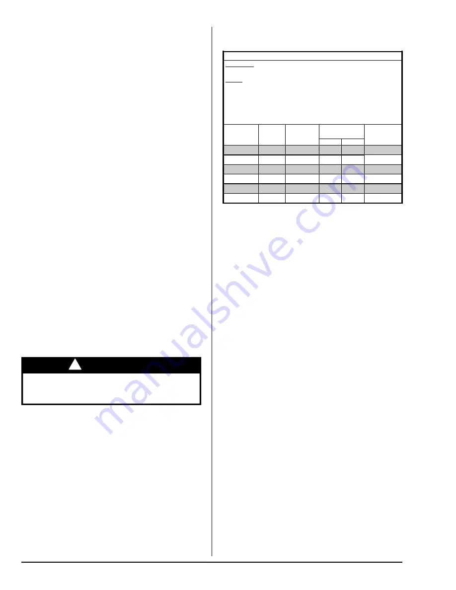
Electrical Service Specifications
Gas Models Only

ELECTRICAL SERVICE SPECIFICATIONS (PER POCKET)


IMPORTANT

:


NOTES

: A.

 B.
 
 
 C.

208 VAC AND 230/240 VAC ARE NOT THE SAME.  When
ordering, specify exact voltage.

When fuses are used they must be dual element, time delay,

current limiting, class RK1 or RK5 ONLY.  Calculate/determine
correct fuse value, by applying either local and/or National
Electrical Codes to listed appliance amp draw data.
Circuit breakers are thermal-magnetic (industrial) motor curve type
ONLY.  For others, calculate/verify correct breaker size according

to appliance amp draw rating and type of breaker used.

Circuit breakers for 3-phase (3ø) dryers must be 3-pole type.

SERVICE

VOLTAGE

PHASE

WIRE

SERVICE

APPROX.

AMP DRAW

CIRCUIT

BREAKER

60 Hz

50 Hz

120

2

12

15

208

2

7

15

220

2

6.8

15

240

2

6.5

15

208

3

3

15

240

3

3.2

15

Summary of Contents for AD-444

Page 1: ...s supplier call the fire department Installation and service must be performed by a qualified installer service agency or the gas supplier AVERTISSEMENT Assurez vous de bien suivre les instructions données dans cette notice pour réduire au minimum le risque d incendie ou d explosion ou pour éviter tout dommage matériel toute blessure ou la mort Ne pas entreposer ni utiliser d essence ni d autres v...

Page 2: ...__________________________________________ ____________________________________________________________________________________________________ Replacement parts can be obtained from your reseller or the ADC factory When ordering replacement parts from the factory you can FAX your order to ADC at 1 508 678 9447 or telephone your order directly to the ADC Parts Department at 1 508 678 9000 Please s...

Page 3: ...ld be supervised if near dryer s in operation Under no circumstances should the dryer door switch lint door switch or heat safety circuit ever be disabled Do not modify this appliance The dryer must never be operated with any of the back guards outer tops or service panels removed Personal injury or fire could result The dryer must never be operated without the lint filter screen in place even if ...

Page 4: ...rubber and also may be a fire hazard The possible presence of residual quantities of aggressive or decomposed chemicals in the load may produce damage to the machine and harmful fumes A program should be established for the inspection and cleaning of lint in the burner area exhaust ductwork and area around the back of the dryer The frequency of inspection and cleaning can best be determined from e...

Page 5: ...__________________________________________________________________________________ ___________________________________________________________________________________________________________________________________ ___________________________________________________________________________________________________________________________________ _____________________________________________________...

Page 6: ...10 Optional 2 20 32 cm 1 25 4 cm COMPRESSED AIR CONNECTION N A COMPRESSED AIR VOLUME N A INLET PIPE CONNECTION PER POCKET 1 2 VOLTAGE AVAILABLE N A APPROXIMATE NET WEIGHT APPROXIMATE SHIPPING WEIGHT AIRFLOW PER POCKET EXHAUST CONNECTION DIAMETER PER POCKET COMPRESSED AIR CONNECTION COMPRESSED AIR VOLUME OVEN SIZE PER POCKET kW Btu hr kcal hr VOLTAGE AVAILABLE N A APPROXIMATE NET WEIGHT APPROXIMATE...

Page 7: ...dclaundry com 7 Specifications _____________________________________________________________________ NOTE The manufacturer reserves the right to make changes in specifications at any time without notice or obligation ...

Page 8: ...ing will be necessary The dryer must be installed with adequate clearance for air openings into the combustion chamber IMPORTANT The dryer must be installed in a location environment which the ambient temperature remains between 40 F 4 44 C and 130 F 54 44 C WARNING Excessive Weight Hazard Use two or more people and mechanical equipment to lift move and install dryer Failure to do so can result in...

Page 9: ...g should be level or below dryer cabinet for ease of removing panels during maintenance F Dryers may be positioned sidewall to sidewall however a 1 16 1 5875 mm minimum allowance must be made for the opening and closing of the control door along with the removal of panels during maintenance G 4 inch 10 16 cm maximum Fresh Air Supply Requirements ______ This appliance may only be installed in a roo...

Page 10: ...0 6 in WC 1 48 mb NOTE When the exhaust ductwork passes through a wall ceiling or roof made of combustible materials the opening must be 2 inches 5 08 cm larger than the duct all the way around The duct must be centered within this opening The ductwork for this dryer must be suitable for the appliance category in accordance with national installation regulations of the country of destination Outsi...

Page 11: ...t to the nearest obstruction The length of the ductwork from the dryer to the outside exhaust outlet must not exceed 20 feet 6 09 meters The minimum diameter of this ductwork must be at least 8 inches 20 32 cm when each pocket tumbler is vented individually and 10 inches 25 4 cm when both pockets tumblers are combined Including tumbler dryer elbow connections or elbows used for outside protection ...

Page 12: ...rounding must conform to applicable requirements of the National Electrical Code ANSI NFPA NO 70 LATEST EDITION or in Canada the installation must conform to applicable Canada Standards Canadian Electrical Codes Parts 1 2 CSA C22 1 1990 or LATEST EDITION The ground connection may be to a proven earth ground at the location service panel For added personal safety when possible it is suggested that ...

Page 13: ...system at test pressures in excess of 1 2 psig 3 5 kPa The dryer must be isolated from the gas supply piping system by closing its individual manual shutoff valve during any pressure testing of the gas supply system at test pressures equal to or less than 1 2 psig 3 5 kPa IMPORTANT Failure to isolate or disconnect the dryer from supply as noted can cause irreparable damage to the gas valve voiding...

Page 14: ...as shutoff valve be provided to the gas supply line of each dryer for ease in servicing IMPORTANT When plumbing upper and lower tumblers together as illustrated below supply connection must be a minimum of 3 4 19 05 mm An 1 8 N P T plugged tap accessible for a test gauge connection must be installed in the main gas supply line immediately upstream of each dryer IMPORTANT Pipe joint compounds that ...

Page 15: ...ls and service box covers have been replaced Check the lint door to ensure that it is closed and secured in place Rotate the tumbler by hand to be sure it moves freely Preoperational Test __________________ All dryers are thoroughly tested and inspected before leaving the factory However a preoperational test should be performed before the dryer is publicly used It is possible that adjustments hav...

Page 16: ... open the main door Continuation of the cycle will resume only after the door has been closed and any of the three temperature selection buttons is pressed Upon completion of the drying and cooling cycles the tone buzzer will sound and the dryer will go into the Anti Wrinkle Mode if active for up to 99 minutes or until the main door or lint drawer has been opened IMPORTANT For more detailed inform...

Page 17: ...in writing either by FAX or CERTIFIED MAIL Return Receipt Requested as to the information necessary to process claim If reply is not received by the Warranty Department within 30 days from the FAX letter date then no replacements credits or refunds will be issued and the merchandise will be discarded Routine Maintenance ________________ Cleaning A program and or schedule should be established for ...

Page 18: ...rmostats Lubrication The motor bearings and under normal most conditions the tumbler bearings are permanently lubricated It is physically possible to relubricate the tumbler bearings if you choose to do so even though this practice is not necessary Use Shell Alvania 2 grease or its equivalent The tumbler bearings used in the dryer do not have a grease fitting Provisions are made in the bearing hou...

Page 19: ...____________________________________________________ _____________________________________________________________ _____________________________________________________________ _____________________________________________________________ _____________________________________________________________ _____________________________________________________________ _____________________________________...

Page 20: ...ADC Part No 112174 7 09 02 14 ...

Reviews: