background image

113279 - 9

www.adclaundry.com

9

Domestic Type I

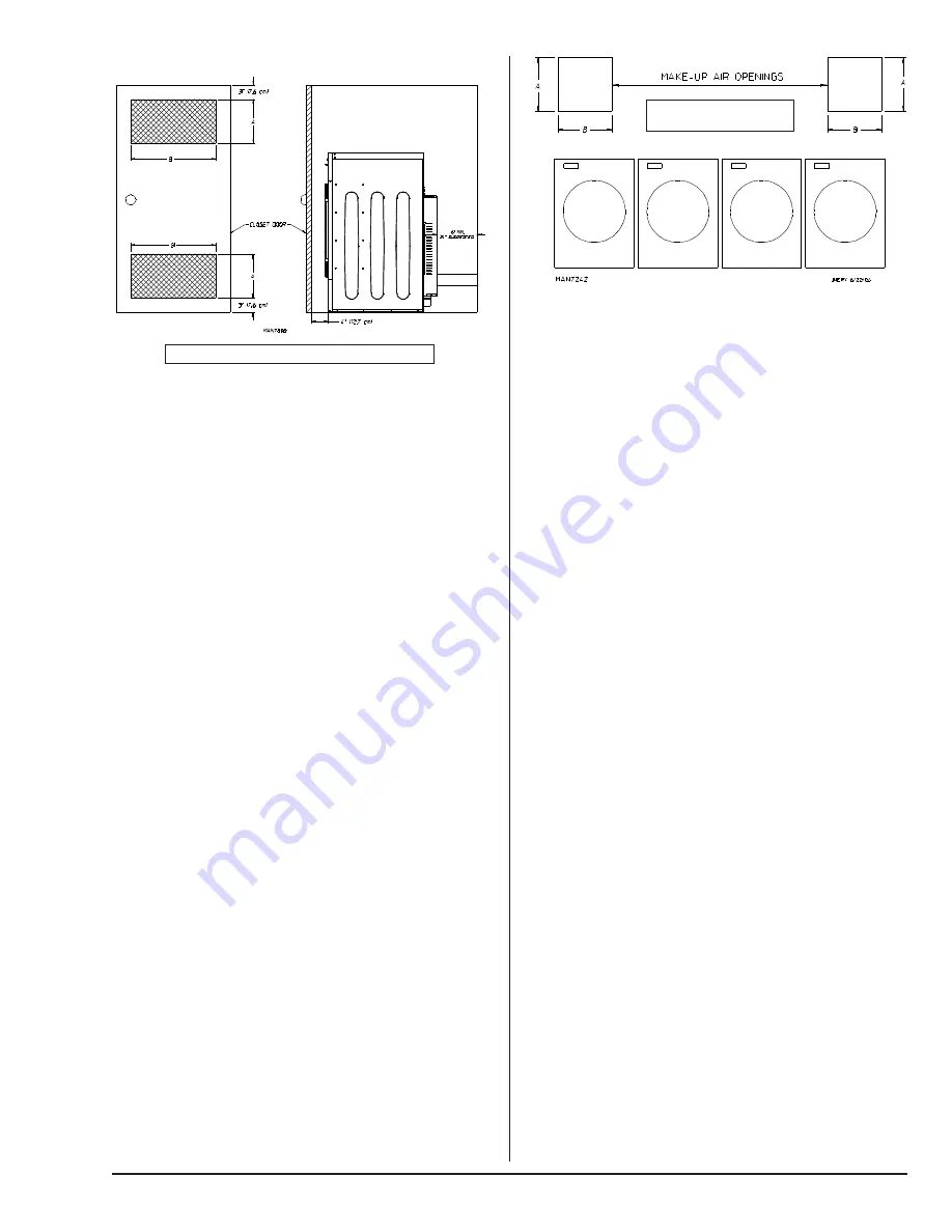
EXAMPLE: Two unrestricted openings measuring 6-inches
by 10-inches (15.24 cm by 25.4 cm) are acceptable.

If a closet door is installed: unobstructed air openings are
required.  The air openings shall be located 3-inches
(7.62 cm) from the lower opening (above floor level) and upper
opening (below ceiling).  The total free area of the air openings
in the door shall not be less than 130 inch

2

 (838.708 cm

2

).

Louvered doors with equivalent air openings are acceptable.

No other fuel-burning appliance shall be installed in the same
closet as the dryer.

Fresh Air Supply Requirements ______

This appliance may only be installed in a room that meets
the appropriate ventilation requirements specified in the
national installation regulations.

When the dryer is operating, it draws in room air, heats it,
passes this air through the tumbler, and exhausts it out of
the building.  Therefore, the room air must be continually
replenished from the outdoors.  If the make-up air is
inadequate, drying time and drying efficiency will be adversely
affected.  Ignition problems may result, as well as premature
motor failure from overheating.  The dryer must be installed
with provisions for adequate combustion and make-up air
supply.

Air supply (make-up air) must be given careful consideration
to ensure proper performance of each dryer.  Fresh air
ventilation openings shall not be blocked and/or sealed.  As
a general rule, an unrestricted air entrance from the outdoors
of 26 inch

2

 (168 cm

2

) for each dryer.  (Based on 1 inch

2

[6.5 cm

2

] per 1,000 Btu [252 kcal].)

It is not necessary to have a separate make-up air opening
for each dryer.  Common make-up air openings are
acceptable.  However, they must be set up in such a manner
that the make-up air is distributed equally to all the dryers.

To compensate for the use of registers or louvers used over
the openings, this area must be increased by approximately
33%.  Make-up air openings should not be located in an area
directly near where exhaust vents exit the building.

Allowances must be made for remote or constricting
passageways or where dryers are located at high altitudes
or predominantly low pressure areas.

NOTE: Component failure due to dry cleaning solvent
fumes will void the warranty.

EXAMPLE: For a bank of four dryers, two unrestricted
openings measuring 10-inches by 6-inches (25.4 cm by 15.24
cm) are acceptable.

IMPORTANT: Make-up air must be free of dry cleaning
solvent fumes.  Make-up air that is contaminated by dry
cleaning solvent fumes will result in irreparable damage to
the motors and other dryer components.

Exhaust Requirements _______________

Exhaust ductwork should be designed and installed by a
qualified professional.  Improperly sized ductwork will create
excessive back pressure, which results in slow drying,
increased use of energy, and shutdown of the burner by the
burner hi-limits or blower housing hi-limit protector thermostat.
The dryer must be installed with a proper exhaust duct
connection to the outside.

The dryer shall not be exhausted into any gas vent, chimney,
wall, ceiling or concealed space of a building.

The design of the flue system shall be such that any
condensate formed when operating the appliance from cold
shall either be retained and subsequently re-evaporated or
discharged.

CAUTION: This dryer produces combustible lint and
must be exhausted to the outdoors.

Improperly sized or installed exhaust ductwork can
create a potential fire hazard.

The ductwork should be laid out in such a way that the
ductwork travels as directly as possible to the outdoors with
as few turns as possible.  There should be a minimum
6-inch (15.24 cm) clearance between the back guard and
the first bend in the ductwork for ease of servicing.  Single or
independent dryer venting is recommended.  It is suggested
that the use of 90° turns be avoided; use 30° and/or 45° bends
instead.  The radius of the elbows should preferably be
1-1/2 times the diameter of the duct.  All ductwork should be
smooth inside with no projections from sheet metal screws
or other obstructions, which will collect lint.  When adding
ducts, overlap the duct being connected.  All ductwork joints
must be taped to prevent moisture and lint from escaping
into the building.  Back draft dampers must be installed in all
commonly ducted systems.  Inspection doors should be
installed at strategic points in the exhaust ductwork for
periodic inspection and cleaning of lint from the ductwork.

A = 6-inches (15.24 cm)  B = 10-inches (25.4 cm)

A = 10-inches (25.4 cm)
B = 6-inches (15.24 cm)

Summary of Contents for AD22

Page 1: ...s L installation et l entretien doivent être assurés par un installateur ou un service d entretien qualifié ou par le fournisseur de gaz WARNING FIRE OR EXPLOSION HAZARD Failure to follow safety warnings exactly could result in serious injury death or property damage Do not store or use gasoline or other flammable vapors and liquids in the vicinity of this or any other appliance WHAT TO DO IF YOU ...

Page 2: ...your order is processed accurately and promptly These instructions are only valid if the following country code is on the appliance If this code is not present on the appliance it is necessary to refer to the technical instructions which will provide the necessary information concerning the modification of the appliance to the condition of use for the country In accordance with EN ISO 3166 1 the n...

Page 3: ...cher Des erreurs de câblage peuvent entraîner un fonctionnement inadéquat FOR YOUR SAFETY Do not dry mop heads in the dryer Do not use dryer in the presence of dry cleaning fumes The dryers must not be installed or stored in an area where it will be exposed to water and or weather The wiring diagram for the dryer is located behind the control panel Table of Contents __________________ WARNING Chil...

Page 4: ...e oil paint or wax Explosion could result Items that have been spotted or soaked with vegetable or cooking oil constitute a fire hazard and should not be placed in a tumble dryer Do not dry mop heads Contamination by wax or flammable solvents will create a fire hazard WARNING Do not use heat for drying articles that contain plastic foam sponge rubber or similarly textured rubber materials Drying i...

Page 5: ...ion of this appliance may affect the operation of other types of gas appliances which take their air for safe combustion from the same room If in doubt consult the appliance manufacturer s Use this dryer only for its intended purpose drying fabrics The Cool Down Cycle of tumble dryers should be used to reduce the temperature of the items They should not be removed from the tumble dryer or piled or...

Page 6: ...TION 3 8 M N P T VOLTAGE AVAILABLE 220 240V 1ø 50 60 Hz APPROXIMATE NET WEIGHT 151 lb 68 49 kg APPROXIMATE SHIPPING WEIGHT 171 lb 77 56 kg AIRFLOW 60 Hz 220 cfm 6 23 cmm 50 Hz 183 cfm 5 19 cmm EXHAUST CONNECTION DIAMETER 4 10 16 cm COMPRESSED AIR CONNECTION N A COMPRESSED AIR VOLUME N A OVEN SIZE kW Btu hr kcal hr 4 1 13 843 3 488 5 0 17 065 4 300 5 4 18 430 4 644 VOLTAGE AVAILABLE N A APPROXIMATE...

Page 7: ...dclaundry com 7 Specifications _____________________________________________________________________ NOTE The manufacturer reserves the right to make changes in specifications at any time without notice or obligation ...

Page 8: ... exhaust venting can be achieved as noted in this manual refer to Exhaust Requirements section IMPORTANT The dryer should be located where a minimum amount of exhaust ducting will be necessary The dryer must be installed with adequate clearance for air openings into the combustion chamber CAUTION This dryer produces combustible lint and must be exhausted to the outdoors Every 6 months inspect the ...

Page 9: ...ssure areas NOTE Component failure due to dry cleaning solvent fumes will void the warranty EXAMPLE For a bank of four dryers two unrestricted openings measuring 10 inches by 6 inches 25 4 cm by 15 24 cm are acceptable IMPORTANT Make up air must be free of dry cleaning solvent fumes Make up air that is contaminated by dry cleaning solvent fumes will result in irreparable damage to the motors and o...

Page 10: ...ed sheet steel not less than 26 gauge 0 0195 inches 0 50 mm thick The ductwork for this appliance must be suitable for the appliance category in accordance with national installation regulations of the country of destination Outside Ductwork Protection To protect the outside end of the horizontal ductwork from the weather a 90 elbow bent downward should be installed where the exhaust exits the bui...

Page 11: ...a Canadian Electric Code CSA C22 1 IMPORTANT Failure to comply with these codes or ordinances and or the requirements stipulated in this manual can result in personal injury or component failure NOTE Component failure due to improper installation will void the warranty Each dryer should be connected to an independently protected branch circuit The dryer must be connected with copper wire only Do n...

Page 12: ...onform to applicable requirements of National Electric Code ANSI NFPA 70 or in Canada the installation must conform to applicable Canada Standards Canadian Electric Code CSA C22 1 The ground connection may be to a proven earth ground at the location service panel For added personal safety when possible it is suggested that a separate ground wire size per local codes be connected from the ground co...

Page 13: ...ervice the individual gas supply line of each dryer must have its own manual shutoff valve IMPORTANT The dryer and its individual shutoff valve must be disconnected from the gas supply piping system during any pressure testing of that system at test pressures in excess of 1 2 psig 3 5 kPa for non CE dryers or 50 mb for CE dryers Failure to isolate or disconnect the dryer from supply as noted can c...

Page 14: ... orifice size NOTE Undersized gas supply piping can create a low or inconsistent pressure which will result in erratic operation of the burner ignition system Consistent gas pressure is essential at all gas connections It is recommended that a 3 4 inch 19 05 mm pipe gas loop be installed in the supply line servicing a bank of dryers An in line pressure regulator must be installed in the gas supply...

Page 15: ...lator vent cap For unregulated propane gas most countries install blocking pin ADC P N 140414 For regulated propane gas some countries remove the white plastic regulator adjustment screw under vent cap Remove spring under screw and replace with spring from kit ADC P N 140416 Replace regulator adjustment screw Install the gas train back into the dryer gas train enclosure Be sure the tab at the rear...

Page 16: ...in dryer s gas supply line Open the panel located just below the loading door Locate the gas train and disconnect the union three electrical plugs and the gas train mounting screws from the burner Carefully slide the gas train out of the gas train enclosure The carbon ignitor located at the far end of the gas train is very fragile Remove two burner tube mounting screws and remove burner tube in or...

Page 17: ...uits Make a complete operational check of all safety related circuits Door Switch es Hi Limit Thermostats Make a complete operational check of all operating controls Tumbler Coating The tumbler is treated with a protective coating We suggest dampening old garments or cloth material with a solution of water and nonflammable mild detergent and tumbling them in the tumbler to remove this coating Micr...

Page 18: ...al dryer NOTE Be sure to include the installation date when returning the warranty card s Warranty For a copy of the commercial warranty covering your particular dryer s contact the reseller from whom you purchased the equipment and request a dryer warranty form If the reseller cannot be contacted or is unknown warranty information can be obtained from the factory by contacting the Warranty Depart...

Page 19: ...ature sensor area WARNING To avoid the hazard of electrical shock discontinue electrical supply to the dryer 90 Days Remove lint from gas valve burner area with a dusting brush or vacuum cleaner attachment Clean any lint accumulation in and around the motor s casing opening NOTE To prevent damage avoid cleaning and or touching ignitor flame probe assembly Every 6 Months Inspect and remove lint acc...

Page 20: ...lows the manufacturer to gather information on your particular dryer 3 Type of Heat This describes the type of heat for your particular dryer gas either natural gas or propane gas electric or steam 4 Heat Input For Gas Dryers This describes the heat input in British thermal units per hour Btu hr or kilowatts kW 5 Orifice Size For Gas Dryers Gives the number drill size used 6 Electric Service This ...

Page 21: ...__________________________________________________ _________________________________________________________________________________________________________________________________ _________________________________________________________________________________________________________________________________ _________________________________________________________________________________________...

Page 22: ...ADC Part No 113279 9 06 16 22 ...

Reviews: