E-2
Campus-REX RS Interface Card User Manual
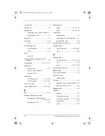
Campus-768 ......................................... 1-2
Campus-E1 ........................................... 1-2
Campus-Star
connecting to an ASCII terminal 3-3
installing the card ........................ 2-3
Campus-T1 ........................................... 1-2
circuit ID ............................................ 5-19
LCD .......................................... 4-12
clearing loopbacks
ASCII terminal .......................... 5-22
LCD .......................................... 4-11
CMU
See LCD
communications settings for ASCII
terminal ............................................ 3-5
compatibility ...................... 1-2 to 1-5, 2-1
configuring
remote unit .................................. 5-3
See also ASCII terminal
connecting
ASCII terminal ..................3-2 to 3-5
Ethernet cable ...................2-4 to 2-6
cross-over cable ................................... 2-4
current HDSL status ...................6-2 to 6-6
D
date ..................................................... 5-18
default configuration settings
.......................................5-5 to 5-6
restoring on LCD ........................ 4-3
Default Router
bridge ............................ 3-21 to 3-23
router ............................. 3-23 to 3-28
desktop unit
compatibility ............................... 2-1
connecting an ASCII terminal .... 3-3
installing the card ....................... 2-2
downloading new firmware ............... 5-24
dropped frames
ASCII terminal ................. 6-8 to 6-9
LCD .......................................... 4-14
E
Encapsulation
ASCII terminal ............. 3-21 to 3-23
LCD .......................................... 3-20
router ............................. 3-23 to 3-28
encapsulation protocols ..................... 7-15
Enter button ........................................ 4-2
error trap generation ............................ 5-9
errored second
See ES alarm
ES alarm .............................................. 4-5
threshold on an ASCII terminal 5-15
threshold on the LCD ................. 4-6
Escape button ...................................... 4-2
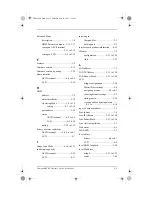
Ethernet
address ........................................ 7-9
checking line status ..................... 2-7
connecting the cable ......... 2-4 to 2-6
port address ............................... 3-26
status ......................................... 4-13
CAD1069i5.book Page 2 Thursday, May 30, 2002 7:32 AM

