background image

ADCP-75-112 

 Issue 3 

 August 2001 

Page 5 

©

 2001, ADC Telecommunications, Inc. 

1.2 Antenna 

Options 

Various

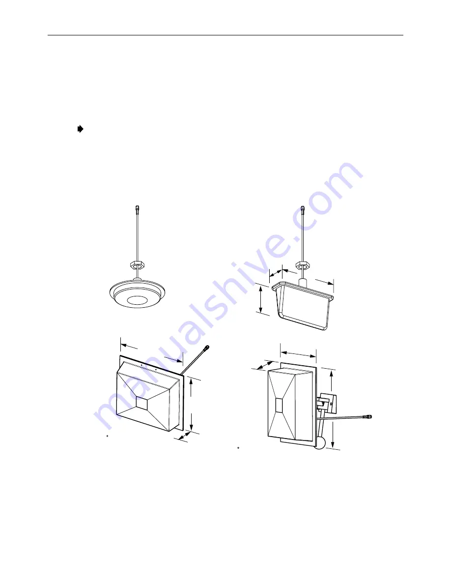
 antennas, shown in Figures 3 and 4, are available from ADC for use with the DRU. 

All

 antennas include a 6 foot (1.8 m) long 50-ohm coaxial cable (equipped with SMA male 

connector)

 for connection to the DRU. The DRU is equipped with an SMA female connector 

for

 connecting the antenna cable. 


  Note: To comply with Maximum Permissible Exposure (MPE) requirements, antennas must 

be

  installed  to  provide at least 20 centimeters (8 inches) of separation from all persons per 

FCC

 47 CFR Part 2.1091.  

DIAMETER - 6.14 INCH (156 MM)
DEPTH - 1.05 INCH (27 MM)

7.26 INCHES

(184 MM)

3.88 INCHES

(99 MM)

2.26 INCHES

(57 MM)

8.65 INCHES
(220 MM)

6.55 INCHES

(166 MM)

2.38 INCHES

(60 MM)

7.90 INCHES

(201 MM)

2.38 INCHES

(60 MM)

8.65 INCHES (220 MM)

4 dBi GAIN

CEILING-MOUNT

HALLWAY

2.5 dBi GAIN CEILING-MOUNT

OMNIDIRECTIONAL

8 dBi GAIN

70  DIRECTIONAL PANEL

(WALL-MOUNT)

7.5 dBi GAIN

90  DIRECTIONAL PANEL

(CORNER MOUNT)

MOUNTING BASE
LENGTH - 3.85 INCHES
                     (98 MM)

ALL ANTENNAS ARE EQUIPPED WITH

A 72-INCH RG58/U CABLE TERMINATED

 WITH A MALE SMA CONNECTOR

MOUNTING STUD
LENGTH - 1.5 INCHES (38 mm)
DIAMETER - 0.875 INCHES (22 MM) 

MOUNTING STUD
LENGTH - 1.5 INCHES (38 mm)
DIAMETER - 0.875 INCHES (22 MM) 

16237-C


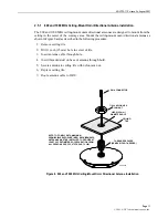
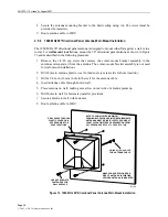
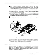
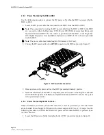
Figure 3. 800 MHz DRU Antenna Options 


Summary of Contents for Digivance ICS 1900

Page 1: ...ION 3 1 1 Digital Remote Unit 3 1 2 Antenna Options 5 1 3 AC DC Power Converter 6 2 INSTALLATION PROCEDURE 7 2 1 Tools and Materials 7 2 2 Unpacking and Inspection 8 2 3 Frequency Band Selection 1900...

Page 2: ...ble hazard and then explains what may happen if the hazard is not avoided The admonishments in the form of Dangers Warnings and Cautions must be followed at all times These warnings are flagged by use...

Page 3: ...e 1 Digital Remote Unit The DRU is equipped with four integral mounting feet that allow it to be mounted on any flat horizontal or vertical surface A typical location for mounting the DRU would be abo...

Page 4: ...of the connectors and the LED that are provided on the DRU front and rear panels The DRU user interface points are indicated in Figure 2 and described in Table 1 16421 A REAR VIEW FRONT VIEW 4 ANTENN...

Page 5: ...from all persons per FCC 47 CFR Part 2 1091 DIAMETER 6 14 INCH 156 MM DEPTH 1 05 INCH 27 MM 7 26 INCHES 184 MM 3 88 INCHES 99 MM 2 26 INCHES 57 MM 8 65 INCHES 220 MM 6 55 INCHES 166 MM 2 38 INCHES 60...

Page 6: ...5 INCHES 64 MM 7 5 dBi GAIN 90 DIRECTIONAL PANEL COMBINATION WALL AND CORNER MOUNT Figure 4 1900 MHz DRU Antenna Options 1 3 AC DC Power Converter The DRU may be powered locally by the AC DC converte...

Page 7: ...up and test procedures 2 1 Tools and Materials The following tools are required in order to complete the procedures in this instruction Box cutter Pencil or scribe Medium size flat bladed screwdriver...

Page 8: ...one of four frequency bands A DIP switch is provided on the underside of the DRU for selecting the required frequency band Use the following procedure to set the DIP switch to provide the required DR...

Page 9: ...ation area must be open to the building s interior air space If a portable flexible antenna will be installed allow a minimum of 9 inches 229 mm clearance along the surface with the antenna Note In mo...

Page 10: ...ssible Exposure MPE requirements antennas must be installed to provide at least 20 centimeters 8 inches of separation from all persons per FCC 47 CFR Part 2 1091 Separate procedures are provided for m...

Page 11: ...ill 1 inch 25 mm hole in center of tile 3 Insert antenna cable through hole 4 Insert threaded stud on base of antenna through hold 5 Secure antenna to ceiling tile with nylon jam nut 6 Replace ceiling...

Page 12: ...t threaded stud on base of antenna through hole 5 Secure antenna to ceiling tile with nylon jam nut 6 Orient antenna so flat sides are perpendicular with hallway walls 7 Replace ceiling tile 8 Route a...

Page 13: ...le through hole in wall 4 Place antenna on wall making sure arrow on rear side of antenna points up 5 Drill holes in wall for fasteners installer provided 6 Secure antenna to wall with fasteners 7 Rou...

Page 14: ...Secure base assembly to wall with fasteners 4 Drill 5 8 inch 16 mm hole in wall for antenna cable 5 Insert antenna cable through hole in wall 6 Reinstall antenna on base assembly 7 Direct antenna tow...

Page 15: ...where the antenna will be mounted If using a ceiling tile rail for mounting the antenna the hole should be next to the tile rail 3 Insert the antenna cable through the hole in ceiling tile 4 If using...

Page 16: ...stallations 2 Drill holes in antenna plastic cover for fasteners see rear side for hole location 3 Drill a 5 8 inch 16 mm hole in the wall for the antenna cable 4 Insert antenna cable through hole in...

Page 17: ...he corner mount bracket 3 Drill holes in wall for corner mount bracket fasteners installer provided 4 Drill a 5 8 inch 16 mm hole in wall for antenna cable 5 Secure corner mount bracket to wall with f...

Page 18: ...by a small form factor LC type optical transceiver which is mounted on the DRU front panel One side of the transceiver provides the optical fiber connection for the forward path downlink signal The o...

Page 19: ...ed as shown Note When viewing the DRU optical transceiver from the front the forward path port is on the right RX and the reverse path port is on the left TX OPTICAL TRANSCEIVER OPTICAL CONNECTOR 1645...

Page 20: ...meters 1 641 feet 2 Connect the DC power cable to the 48 VDC connector on the DRU as shown in Figure 17 POWER PORT POWER CONNECTOR 16453 A 1 8 Figure 17 DC Power Cable Connection 3 Dress and secure t...

Page 21: ...connector on the AC DC converter see Figure 18 5 Route the plug end of the power cord to the specified AC outlet per the system design plan and connect plug to outlet Warning Be sure to check the nam...

Page 22: ...Specification and Application Training Product Specific Installation and Operation Assistance Troubleshooting and Repair Product Return Department Extension 63478 E Mail repair return adc com ADC Ret...

Reviews: