ADCP-50-404 • Issue 2 • November 1998
Page 2
© 1998, ADC Telecommunications, Inc.
1. GENERAL
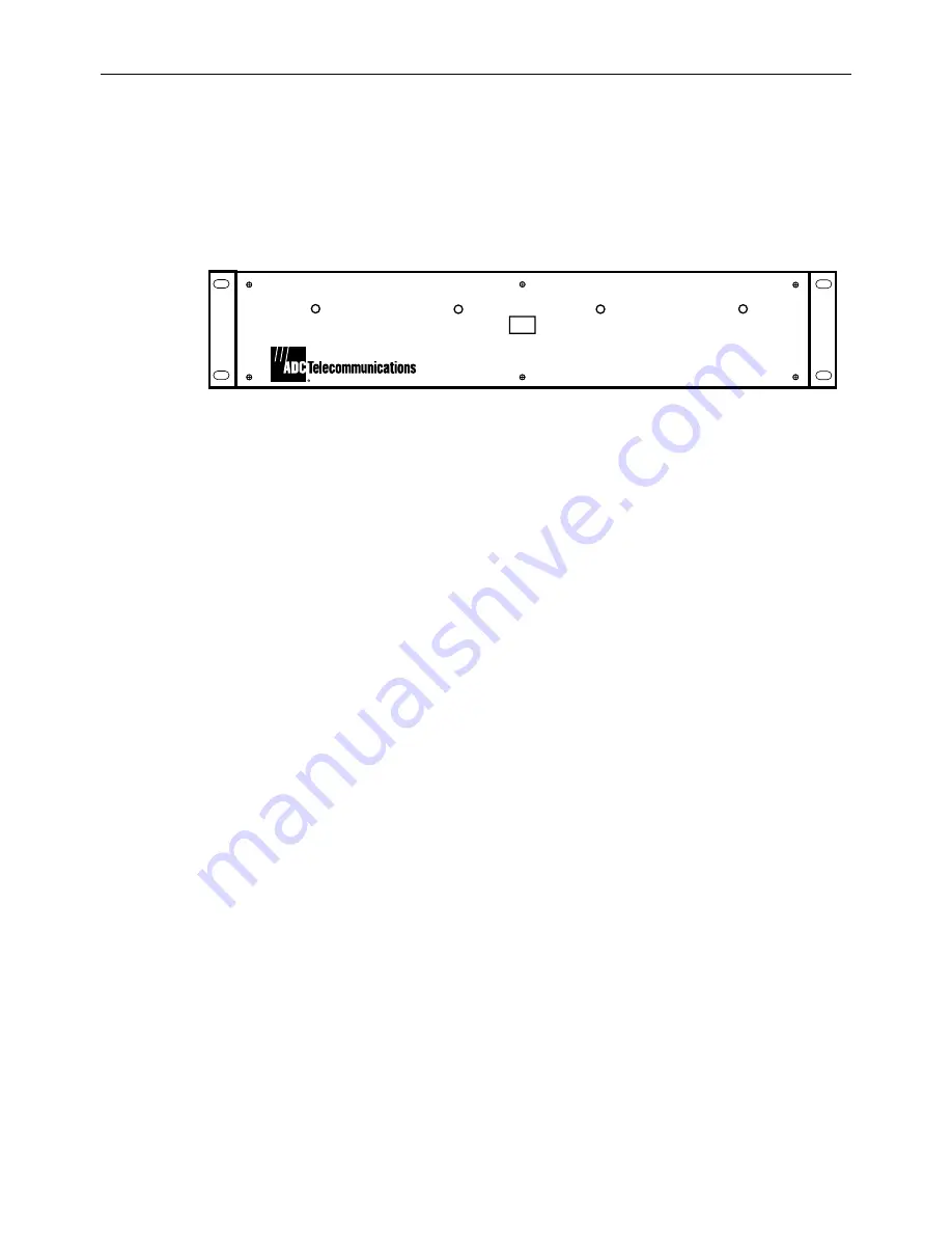
The DMPS-10CE Power Supply, as shown in
Figure 1
, is a rack mounted power supply
pro5, +12, and –12 Volts dc. It is expandable (with the basic power supply and up to
three DMPS-10EXP/CE expansion modules) to a total of four dc power sources each
pro 5, + 12 and –12 volts.
8257-A
AC
DC OUT 1
DC OUT 2
DC OUT 3
DC OUT 4
DMPS-10CE POWER SUPPLY
Figure 1. DMPS-10CE Power Supply
The power supply including the basic unit measures 3.5
19 11 inches (8.9 48.3 27.94
cm). Each DMPS-l0EXP/CE expansion module measures 3.5
3.9 9.22 inches (8.9 9.91
23.5 cm) and fits into the basic power supply.
The DMPS-10CE has EN 60950 classification for use in Europe.
2. DETAILED DESCRIPTION
2.1 DMPS-10CE Power Supply (Basic)
The DMPS-10CE power supply is designed for the ADC Telecommunications PatchSwitch
system but will work well with other applications. It will operate with any input voltage
between 190 and 240 volts ac and any frequency between 48 and 62 Hz. Manual adjustments
are not necessary. Only one ac input is necessary per shelf for up to four dc power sources (the
basic unit plus three expansion modules).
Input ac power is supplied via a six-foot, three-conductor power cord equipped with a
standard three prong with ground plug on one end and a special IEC 3-pin connector on the
other. The special IEC 3-pin connector plugs into the back of the basic DMPS-l0CE power
supply. Fuses are installed at the factory as described in “Power-Up of the DMPS-l0CE Power
Supply” section, page 6 of this manual.
There are four LED indicator lights on the front of the unit to indicate whether the power
supply and expansion modules are operating. The right-most LED (marked “DC OUT 1”) is
for the basic unit. Each of the three others (marked DC OUT 2, 3 & 4) displays the condition
of the expansion modules.


