background image

ADCP-80-325 

 Issue 4 

 January 2001

Page 8

2001, ADC Telecommunications, Inc.

TL

T
R

T1
R1

OUT

IN

TL
T
R
T1
R1

OUT

IN

1

5

10

15

20

25

30

35

40

45

50

55

60

65

70

75

80

85

90

95

100

8385-A

REMOVABLE CABLE TRAY

(NOT MOUNTED BY ADC)

22.312 IN. 56.7 CM)

(REF)

23.00 IN. 58.4 CM)

(REF)

29.30 IN. 

±

 .25 IN.

(74.4 CM 

±

 .6 CM)

3.00 IN.

(7.64 CM)

(REF)

4.00 IN.

(10.16 CM)

MAX

1.60 IN.

(4.06 CM)

(REF)

19.80 IN.

(50.3 CM)

(REF)

G

W

BL

W

O

G

W

BL

W

O

G

W

BL

W

O

G

W

BL

W

O

W

W

W

W

W

G

W

BL

W

O

G

W

BL

W

O

W

W

W

W

W

G

W

BL

W

O

G

W

BL

W

O

W

W

W

W

W

G

W

BL

W

O

G

W

BL

W

O

TL

T

R

T1

R1

TL

T

R

T1

R1

OUT

IN

OUT

IN

1

5

95

100

COLOR SCHEME DETAIL

(EVERY 5TH CIRCUIT IS WHITE)

W

BL

O
G

WHITE
BLUE
ORANGE
GREEN

COLOR CHART

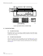
Figure 4. Typical Information Shown on Installation Drawing

4.3  Cross-Aisle Panel Cabling

4.3.1  Cross-Aisle Tie Cable Type

Recommended cable for cross-aisle cable ties is shielded twisted pair cable 26 AWG, similar
to AT&T 1249 cable. Separate cable should be used for each direction of the circuit. Ground
the cable shield at one end only.

4.3.2  Cross-Aisle Tie Cable Connections

Connect the tie cables to the wire-wrap terminals on the Cross-Aisle Panels. 

Figures 2

 and 

3

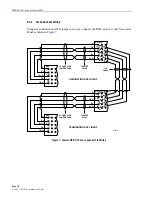
show Cross-Aisle Panel wiring in typical multi-lineup systems. One recommended method of
wiring is to connect the OUT terminals in one lineup to the IN terminals of the other lineup as
shown in 

Figure 5

.

Summary of Contents for DSX-1

Page 1: ...stallation Drawing 7 4 3 Cross Aisle Panel Cabling 8 4 3 1 Cross Aisle Tie Cable Type 8 4 3 2 Cross Aisle Tie Cable Connections 8 4 4 Cross Connects 9 4 4 1 Cross Connect Wire Type 9 4 4 2 Cross Connect Length 9 4 4 3 Cross Connect Wiring 10 5 CUSTOMER INFORMATION AND ASSISTANCE 13 INTRODUCTION This manual describes the ADC DSX 1 Cross Aisle Panels and their use in multiple lineup DSX 1 Systems Re...

Page 2: ...is manual describes ADC s DSX 1 Cross Aisle Panels and their application in multi lineup DSX 1 Systems This manual also provides complete instructions for installing the Cross Aisle Panel in a bay Procedures for mounting cabling and wiring the panels in the bay are included The manual includes recommended inter lineup wiring configurations and installation instructions It is recommended that the e...

Page 3: ... Cross Aisle Wiring In Figure 2 all Cross Aisle Panels are cabled between the same numbered bays in each lineup In this direct wiring design cross connect wires are run from the Cross Aisle Panel in the bay where they originate to the associated Cross Aisle Panel in the same numbered bay of another lineup This means that no horizontal wireway is required in the originating bay The cross connect is...

Page 4: ...NE 2 8384 A Figure 3 DSX 1 1C Cross Aisle Panel Two Zone Wiring Table 1 shows point to point information for interconnecting three lineups with 20 bays each In this example 200 cross aisle circuits are provided in each bay with 50 circuit complements distributed as shown in Figure 3 Zoned cross aisle tie cabling systems may contain as many zones as desired However each zone should have the same nu...

Page 5: ... 3 17 151 200 2 02 1 12 151 200 2 07 1 17 151 200 2 02 3 02 101 150 2 07 3 07 101 150 2 02 3 12 1 50 2 07 3 17 1 50 3 02 1 12 51 100 3 07 1 17 51 100 3 02 2 12 151 200 3 07 2 17 151 200 1 03 2 03 51 100 1 08 2 08 51 100 1 03 2 13 101 150 1 08 2 18 101 150 1 03 3 03 1 50 1 08 3 08 1 50 1 03 3 13 151 200 1 08 3 18 151 200 2 03 1 13 151 200 2 08 1 18 151 200 2 03 3 03 101 150 2 08 3 08 101 150 2 03 3...

Page 6: ...51 100 1 14 2 14 1 50 1 19 2 19 1 50 1 14 3 14 101 150 1 19 3 19 101 150 2 14 3 14 51 100 2 19 3 19 51 100 1 15 2 15 1 50 1 20 2 20 1 50 1 15 3 15 101 150 1 20 3 20 101 150 2 15 3 15 51 100 2 20 3 20 51 100 The zoned cross aisle cabling system results in shorter jumpers and thereby reduces horizontal jumper pileup 3 3 Ratio of Cross Aisle Ties The ratio of cross aisle ties to the number of equipme...

Page 7: ...storm When installing or modifying telephone lines disconnect lines at the network interface before working with uninsulated lines or terminals 4 1 Panel Mounting Install all Cross Aisle Panels in the assigned bay locations using 12 24 1 2 inch mounting screws Note The 12 24 1 2 inch mounting screws must be ordered separately 4 2 Installation Drawing Each panel is shipped with an installation draw...

Page 8: ...00 COLOR SCHEME DETAIL EVERY 5TH CIRCUIT IS WHITE W BL O G WHITE BLUE ORANGE GREEN COLOR CHART Figure 4 Typical Information Shown on Installation Drawing 4 3 Cross Aisle Panel Cabling 4 3 1 Cross Aisle Tie Cable Type Recommended cable for cross aisle cable ties is shielded twisted pair cable 26 AWG similar to AT T 1249 cable Separate cable should be used for each direction of the circuit Ground th...

Page 9: ...rs and a binder wire all twisted together 4 4 2 Cross Connect Length The DSX cross connect wires add to the overall digital signal losses depending on the wire length To assure reliable signal levels the recommended maximum cross connect length including cross aisle cables is 85 feet as shown in Figure 6 Always cross connect from OUT to IN and IN to OUT 8387 A DSX JACK CROSS AISLE PANEL CROSS CONN...

Page 10: ...sle Panel as shown in Figure 7 DSX TL T R T R OUT IN X AISLE TL T R T R OUT IN G BL BL W OR OR W G OR OR W BL BL W 5 CONDUCTOR JUMPER WIRE TWISTED PAIRS TIE CABLE DSX TL T R T R OUT IN X AISLE TL T R T R OUT IN G BL BL W OR OR W G OR OR W BL BL W 5 CONDUCTOR JUMPER WIRE TWISTED PAIRS ORIGINATING DSX LINEUP TERMINATING DSX LINEUP 8388 A Figure 7 Typical DSX 1 1C Cross Connect Tie Wiring ...

Page 11: ...s aisle tie circuit to the OUT on the DSX circuit Remove any discontinued jumpers by disconnecting each end and cutting off the bare ends Remove each end of the jumper from the vertical wireways and carefully remove the jumper from the horizontal wireway by pulling at either end This method of removal allows the jumper to be removed without snagging or placing undo strain on the remaining jumpers ...

Page 12: ...AYS B ALL JUMPERS IN THE RIGHT HAND SIDE OF THE CROSS CONNECT FIELD SHOULD ENTER AND LEAVE THE BAY FROM THE RIGHT VERTICAL WIREWAYS C ALL INTRABAY CROSS CONNECTS SHOULD USE THE VERTICAL RINGS D ALL INTERBAY CROSS CONNECTS SHOULD USE THE HORIZONTAL WIREWAYS E ALL JUMPERS ORIGINATING IN THE UPPER HALF OF THE CROSS CONNECT FIELD SHOULD ROUTE VIA THE UPPER HORIZONTAL WIREWAYS F ALL JUMPERS ORIGINATING...

Page 13: ...t Specification and Application Training Product Specific Installation and Operation Assistance Troubleshooting and Repair Product Return Department Extension 63748 E Mail repair return adc com ADC Return Authorization number and instructions must be obtained before returning products Product information may also be obtained using the ADC web site at www adc com or by writing ADC Telecommunication...

Reviews: