R
EAR
-P
ANEL
C
ABLE
C
ONNECTIONS
Make the following rear-panel cable connections:
1
Connect the cable containing the SHDSL pair to the SHDSL line connector.
2
If the customer equipment uses 75
Ω
coaxial cable, connect the equipment's output
cable to the 75
Ω
IN connector. Connect the equipment's input cable to the 75
Ω
OUT
connector.
3
If the customer equipment uses 120
Ω
twisted-pair cable, connect the cable to the
120
Ω
\ALARM connector.
4
If the customer equipment uses an Nx64k serial interface (V.35, V.36, RS-449,
RS-530, or X.21), connect its cable to the DATA PORT connector.
5
If using an external power-fail alarm, fabricate a cable that connects alarm-relay
pins 5 (NC), 7 (NO), and 14 (C) of the ALARM connector to the external alarm (the
ALARM connector is designated 120
Ω
\ALARM on ETU-911A and ETU-914A).
DSL S
ELF
T
EST
AND
L
INK
U
P
The LTU-configured unit holds the configuration settings for both itself and the remote
NTU-configured unit. As the two units synchronize, the LTU will configure the NTU.
1
Power up the SHDSL unit.
2
Confirm the following:
•
The red ALM LED is on and the green SYNC LED flashes once per second as
the units self-configure and establish synchronization.
•
After approximately 60 seconds, the red ALM LED is off, and the SYNC LED is
a steady green. The unit is now ready for configuration using the console screen
menus displayed on a maintenance terminal at the exchange office.
Other LED functions are described in Table 1.
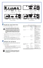
D25F data port
connector
D15F alarm connector
D9F SHDSL line
connector
Power cord
receptacle
On/off
switch
Chassis
ground lug
ETU Front Panel
ETU-912A Rear Panel
On/off
switch
D15F 120 G.703 and
alarm connector
Ω
BNC 75 G.703
in and out connectors
Ω
D9F SHDSL line
connector
Power cord
receptacle
120/75
selector switch
Ω
D25F data port
connector
Chassis
ground lug
ETU-911A Rear Panel
ETU-914A Rear Panel
Local and remote
loopback LEDs
and pushbuttons
V.24 (RS-232)
console port
G.703 bridge jack
(ETU-911A and
ETU-914A only)
SHDSL sync and
alarm LEDs
I/F alarm LED
D15F 120 G.703 and
alarm connector
Ω
BNC 75 G.703
in and out connectors
Ω
D9F SHDSL line
connector
On/off
switch
Power cord
receptacle
120/75
selector switch
Ω
Chassis
ground lug
Primary protection for the SHDSL line must be provided by
the user. Both primary and secondary protection must be
provided by the user if the E1 line runs outside of the building.
Der primaere Schutz des SHDSL Anschlusses muss von der
Benutzerseite aus geregelt werden. Wenn der E1 Anschluss
ausserhalb des Gebaeudes installiert ist, muss der primaere
und sekundaere Schutz von der Benutzerseite aus geregelt
werden.
Copies of the UTU/ETU User Manual (LTPE-UM-3010-xx) or
this publication can be downloaded from the ADC website at
www.adc.com. To order a hard copy, please contact your
sales representative.
Table 1.
Front-Panel LED Functions
LED
Mode
Description
SHDSL SYNC
Steady green
Slow flashing
Off
SHDSL loop is ready to transmit and
receive data.
SHDSL loop acquisition is in
progress.
SHDSL loop is not configured.
SHDSL ALM
Steady red
Pulsing red
Off
Margin is below set threshold (MAL
alarm).
Loop attenuation is above set
threshold (LAL alarm).
Errored seconds count is above set
threshold (ESAL alarm).
Loss of sync word (LOSW alarm).
AC power supply failure (ACPF
alarm) at remote ETU.
Pulses for every ES on the span.
Normal transmit or receive data is in
progress.
I/F ALM
Steady red
Blinking red
Pulsing red
Loss of signal (LOS alarm).
Loss of clock (LOC alarm) due to
loss of TT clock (Nx64k timing).
Loss of external clock (LOC) alarm)
when using EXT timing.
Loss of frame alignment (LFA
alarm).
Remote alarm indication signal (RAI
alram).
Received alarm indication signal
(AIS alarm).
Pulses for every ES on E1 interface.
LOC and REM
LPBK LEDs
(a)
(a) The LOC and REM loopback LEDs are read in unison.
LOC
REM
Off
Off
No loopbacks are active.
Steady yellow
Off
Local DSL analog loopback is active.
Off
Steady yellow
Remote loopback is active.
Blinking yellow
Off
Local interface loopback is active.
Blinking yellow
Blinking yellow
A loopback away from the local
equipment is active.

