DNV Certification, Inc.
REGISTERED FIRM
ISO 9001/TL 9000
Limited Warranty
ADC DSL Systems, Incorporated (“ADC”) warrants that , for a period of sixty (60) months from the date
of shipment, the hardware portion of its products will be free of material defects and faulty workmanship
under normal use. ADC's obligation, under this warranty, is limited to replacing or repairing, at ADC's
option, any such hardware product which is returned during the 60-month warranty period per ADC's
instructions and which product is confirmed by ADC not to comply with the foregoing warranty.
ADC warrants that, for a period of 90 days from the date of purchase, the software furnished with its
products will operate substantially in accordance with the ADC published specifications and
documentation for such software. ADC’s entire liability for software that does not comply with the
foregoing warranty and is reported to ADC during the 90-day warranty period is, at ADC’s option, either
(a) return of the price paid or (b) repair or replace of the software. ADC also warrants that, for a period
of thirty (30) days from the date of purchase, the media on which software is stored will be free from
material defects under normal use. ADC will replace defective media at no charge if it is returned to
ADC during the 30-day warranty period along with proof of the date of shipment.
The transportation charges for shipment of returned products to ADC will be prepaid by the Buyer. ADC
will pay transportation charges for shipment of replacement products to Buyer, unless no trouble is
found (NTF), in which case the Buyer will pay transportation charges.
ADC may use reconditioned parts for such repair or replacement. This warranty does not apply to any
product which has been repaired, worked upon, or altered by persons not authorized by ADC or in ADC's
sole judgment has been subjected to misuse, accident, fire or other casualty, or operation beyond its
design range.
Repaired products have a 90-day warranty, or until the end of the original warranty period—whichever
period is greater.
Modifications
Any changes or modifications made to this device that are not expressly approved by ADC DSL
Systems, Inc. voids the user's warranty.
All wiring external to the product should follow the local wiring codes.
Trademark Information
ADC is a registered trademark and WorldDSL is a trademark of ADC Telecommunications, Inc. Other
product names mentioned in this installation guide are used for identification purposes only and may be
trademarks or registered trademarks of their respective companies.
Copyright Information
© 2002 ADC DSL Systems, Inc. All rights reserved. Information contained in this document is company
private to ADC DSL Systems, Inc., and shall not be modified, used, copied, reproduced or disclosed in
whole or in part without the written consent of ADC.
ADC DSL Systems, Inc.
14402 Franklin Avenue
Tustin, CA 92780-7013
Tel: 714.832.9922
Fax: 714.832.9924
Technical Assistance
Tel: 800.638.0031
Tel: 714.730.3222
Fax: 714.730.2400
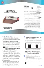
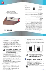
ETU-911A, ETU
-912A,
AND
ETU-914A
The ADC
®
World
DSL™
G.S ETU-9
11A,
ETU-912
A, an
d ET
U-914A
ETSI
Term
inat
ion Un
its (ETU
s)
are
ra
te
sele
cta
ble
Sin
gle
-pai
r High
-spee
d Dig
ital
Subs
crib
er Line (S
HDSL
) card
s hou
sed i
n e
ncl
osures
wi
th
rear-pan
el i
nte
rface and
power con
nec
to
rs for use as stan
dalo
ne deskt
op
u
nit
s
. The
SHDS
L ca
rds co
nform t
o
ITU-T rec
omm
end
atio
n G.9
91
.2
fo
r SHDSL
(referr
ed
to as G.S
HDS
L).
Rate
sele
cta
ble
G.SH
DS
L offe
rs an
ex
tend
ed
tra
nsm
ission
rang
e a
nd
spect
ral
co
mp
atibi
lity with
lead
ing
DSL te
ch
nolo
gies.
Trans
mis
sion
ranges
vary
according
to the data rate
selected,
wire
si
ze, and
noise env
iron
ment. At a
data
rate of 2.048
Mb
ps with nois
e,
the
reach i
s 2.4 km
(1
.4 mile) on 0.4
mm
wire
and 6
.8 k
m (
4.2
miles) on
8 mm
wire
. Reach is
sig
nifican
tly
great
er at lo
we
r
data rates
in r
educed
nois
e enviro
nments
. F
or d
eta
ils, s
ee the UTU/ETU Us
er
Manual, LTPE-UM-3
010-xx
(which can b
e do
wnloaded fr
om the AD
C
website at
www.a
dc.
co
m).
Th
e ET
Us can
b
e con
figure
d as L
ine T
ermi
nat
io
n Unit
s (LT
Us)
or
Net
work
Term
inat
ion Un
its (NTUs). The
defa
ult co
nfigu
ratio
n is NTU.
Th
e NTU-co
nfig
ured E
TU
s are in
stal
led
at
th
e c
ust
omer si
te.
LT
U-con
figu
red
Universal Termina
tio
ns Unit
s, UTU-911
, UT
U-91
2, an
d UTU-91
4, are i
nst
alle
d i
n
excha
nge o
ffice she
lv
es.
To
comp
let
e t
he
G.S
HDSL
trans
mis
sion
sy
stem,
th
e UTUs
and E
TUs
ar
e i
nte
rcon
nect
ed ov
er on
e pair of
tw
ist
ed-
co
pp
er wi
re.
Th
e UTUs acc
ept t
he ex
chang
e offi
ce payl
oad at
th
eir G.
703 or Nx6
4k
p
ort
and
tran
sport th
e pa
yloa
d to
the
ETUs at t
he se
lect
ed
DSL da
ta ra
te.
The DS
L data
ra
te is
dete
rm
in
ed by t
he
nu
mb
er of
64
kbps t
im
e slot
s selec
ted
by th
e user. T
he UT
Us and
ETU
s ha
ve a
DSL d
ata
rate
rang
ing e
ither
fro
m 19
2 kb
ps t
o 2
.0
48
Mb
ps (
G.7
03) o
r
fro
m 19
2 kbps
to 2.30
4 M
bp
s (
Nx6
4k
).
The
ETU
s r
equ
ire
a 50
o
r 60
H
z p
ow
er s
ou
rce
with
a
volta
ge r
an
ge of
1
00
to
240 V
ac.
The ETUs i
nclu
de a p
ower-fail
circ
uit t
hat t
rig
gers a u
ser-co
nfig
ured
alarm a
nd
repo
rts
same t
o t
he e
xch
ange
office
when
an
AC
power fa
ilu
re
occu
rs.
A
PPLIC
ATIO
N
I
NTER
FA
CE
The ETU-91
1A h
as an
E1 G
.703
interface
that can be con
figu
red f
or an
im
ped
an
ce of
75
Ω
unba
lan
ced or 12
0
Ω
balanced.
Data is
stru
ctu
red or
unst
ru
ctured accor
ding
to the G.70
4 framin
g s
tandar
d an
d, op
tionally,
CR
C-4 mu
ltif
ramed accord
ing to the G.7
06 stand
ard.
The ETU-91
2A h
as an
Nx64k s
erial d
ata
po
rt inte
rface with u
ser
-selectab
le
prot
ocols t
hat
conf
orm to
th
e V.3
5, V
.3
6, X
.21,
or RS
-530 (R
S-449
)
standar
ds.
The ETU-91
4A has
both an
E1 G.70
3 interface
and an Nx6
4k
interface, s
harin
g the SHDSL band
width.
Us
e of
this
prod
uct in
a m
an
ne
r o
th
er
than
defin
ed
in th
is
in
stal
la
tio
n g
uid
e may ca
use d
ama
ge t
o eq
uip
men
t o
r i
nju
ry
to
pers
onne
l.
Fa
lls
der Ge
bra
uc
h vo
n die
se
m Pr
oduk
t nic
ht ge
maes
s de
r
Defi
niti
on
im I
nst
alla
tion
s Hand
buch
e
in
ge
ha
lte
n wird
, b
es
teh
t
die
Gefa
hr, d
as
s Sc
hade
n am G
era
et
od
er s
og
ar
Koer
pe
rv
erl
etz
unge
n en
ts
te
he
n ko
ennt
en.
ETU-911A
AND
ETU-91
4A 120/75
O
HM
G.703 S
WIT
CH
S
ETTI
NGS
Th
e rear-pane
l 12
0/75
Ω
Se
lect
or S
witc
h mu
st be
set
fo
r 12
0
Ω
i
f usi
ng a
120
Ω
G.70
3
inte
rface
. The
defa
ult
sett
ing is 7
5
Ω
. The se
ttings fo
r 75
Ω
and
120
Ω
op
erat
io
n are
shown
in
Figu
re
1.
Fig
ure
1.
ET
U-9
11
A a
nd
ETU
-91
4A 12
0/75
Ω
G.70
3 Sw
itc
h S
ett
ings
ETU
E
ARTH
G
RO
UND
C
ONNE
CTION
To
conn
ect t
he E
TU ch
assis t
o ea
rth
ground
:
1
On the
ET
U rear
pan
el, re
mo
ve th
e two
hex
nuts fro
m th
e c
has
sis
gro
un
d lu
g.
2
Pla
ce th
e g
rou
nd wire
ring
-te
rmi
nal on
the ch
assis gr
ound
lug.
3
Secu
re
th
e gro
und wir
e t
o t
he
grou
nd l
ug wi
th t
he tw
o hex n
uts
remo
ved i
n st
ep 1.
4
Attach
th
e ot
her e
nd o
f t
he
grou
nd w
ire
to
ear
th
gro
und.
C
ONTIN
UE
D
The ETU c
has
sis mus
t be
conn
ected to
eart
h groun
d for
protec
tion
of the e
quipm
ent and
for personn
el sa
fety
.
Die G
eraete
Erdung des
ETU mu
ss via
die Haup
t-Erdung
(Erdpo
tentia
l) gu
aran
tiert w
erd
en
, um
das G
era
et zu
schue
tzen und
die Sich
erheits de
s Persona
ls zu
gewa
ehrle
iste
n.
A 12- or 14-g
auge
solid cop
per grou
nd wire is
re
comm
ended
.
Ω
75 switch settings (def
ault)
Ω
120 switch settings
1
2
3
4
1 and 2 = ON
3 and 4 = OFF
All switches
set to OFF
1
2
3
4
Þ
ETU-911A, ETU-912A,
AND
ETU-914A
R
ATE
S
ELECTABLE
G.SHDSL
ETSI T
ERMINATION
U
NITS
W
ORLD
DSL G.S
Q
UICK
I
NSTALLATION
´,D°¶5T¨
1236955
June 21, 2002
Product Catalog: ETU-911A
ETU-912A
ETU-914A
Document: LTPE-QI-3155-01

