SCP-FCS717-022-03H
Installation and Test
FCS-717 List 2B
January 6, 2003
17
Bypass Pairs
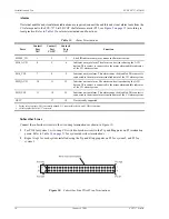
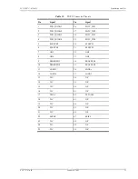
If subscriber drop testing is required, connect the metallic bypass pairs from the RT enclosure to the COT shelf
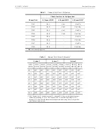
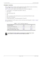
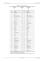
backplane wire-wrap pins as shown in
(refer to
for bypass pair terminations and functions).
Bypass pairs can be connected directly to each PG-Flex system, or shared between other PG-Flex systems by
cascading the pairs between other systems.
Directly Connected Bypass Pairs.
To connect the bypass pairs directly to each system, do the following:
1
For System 1, connect the metallic bypass pair from the Main Distribution Frame (MDF) to wire-wrap posts
BYPASS_1_T (Tip) and BYPASS_1_R (Ring) on the COT shelf (see
2
Repeat step 1 for Systems 2 and 3 using the following bypass pin pairs:
•
BYPASS_2_T, BYPASS_2_R for system 2
•
BYPASS_3_T, BYPASS_3_R for system 3
Shared Bypass Pairs.
To share bypass pairs between PG-Flex systems, do the following:
1
For System
n
, connect the metallic bypass pair from the main distribution frame (MDF) to wire-wrap posts
BYPASS_
n
_T (Tip) and BYPASS_
n
_R (Ring) on the backplane of the first system in the COT shelf sharing
the bypass pair (see
2
Connect the metallic bypass pairs BYPASS_
n
_T and BYPASS_
n
_R on the first COT shelf in the cascade to
the next bypass pair terminations on the next system in the COT shelf sharing the bypass pair.
* Where n is 1 for System 1, 2 for System 2, and 3 for System 3.
† Connecting the inhibit pins of multiple PG-Flex systems that are sharing the same bypass pair prevents other systems from attempting
to use the bypass pair when it is currently being used by another system. The inhibit pin is grounded when the bypass pair is in use, and
-48 Vdc when the bypass pair is inactive.
When metallic bypass pairs are shared between PG-Flex shelves or to other Digital Loop
Carriers (DLC) systems, the INHIBIT lead must be connected between each shelf sharing the
bypass pairs.
Table 12.
HDSL, Test, And Miscellaneous Connectors (Cont.)

