List of Tables
LTPH-SM-1052-04
xii
July 14, 2002
HMS-358 List 5 and List 6
L
IST
OF
T
ABLES
1. Packing List .................................................................................................................................................... 5
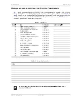
2. System Installation Notes ............................................................................................................................... 5
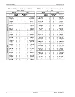
3. Cable Connector Pinout and Color Code (16/16 Cable) .............................................................................. 10
4. Cable Connector Pinout and Color Code (25/7 Cable) ................................................................................ 10
5. J32 Pinouts for 10BASE-2 Interface ............................................................................................................ 19
6. J34 Pinouts for 10BASE-T Interface............................................................................................................ 20
7. J30 Pinouts for DB-25 (Female Connector) OS Interface (DTE) ................................................................ 20
8. J31 Pinouts for DB-25 (Female Connector) AUX Interface (DTE)............................................................. 21
9. System Loopback Definitions ..................................................................................................................... 61
10. Line Unit Alarm Messages ........................................................................................................................... 67
11. Network Addressing..................................................................................................................................... 68
12. Sample Class C IP Address Plan for the HMS-358 ..................................................................................... 69
13. Relay Specifications ..................................................................................................................................... 70
14. HMS-358 List 5 Split Power Shelf .............................................................................................................. 74
15. HMS-358 List 6 Redundant Power Shelf..................................................................................................... 74
16. CUP Parameters Line Descriptions .............................................................................................................. 78
17. System Components ..................................................................................................................................... 82
18. Compliance Standards .................................................................................................................................. 83
19. Signatures ..................................................................................................................................................... 87


