Cabling the Chassis
LTPH-SM-1052-04
12
July 14, 2002
HMS-358 List 5 and List 6
I
NSTALLING
I
NTERFACE
C
ABLES
—DS3
OR
STS-1
TO
DSL
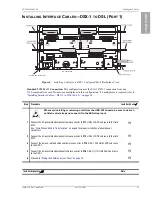
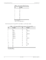
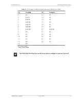
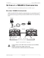
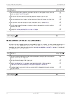
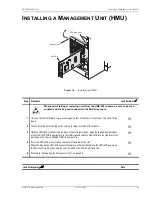
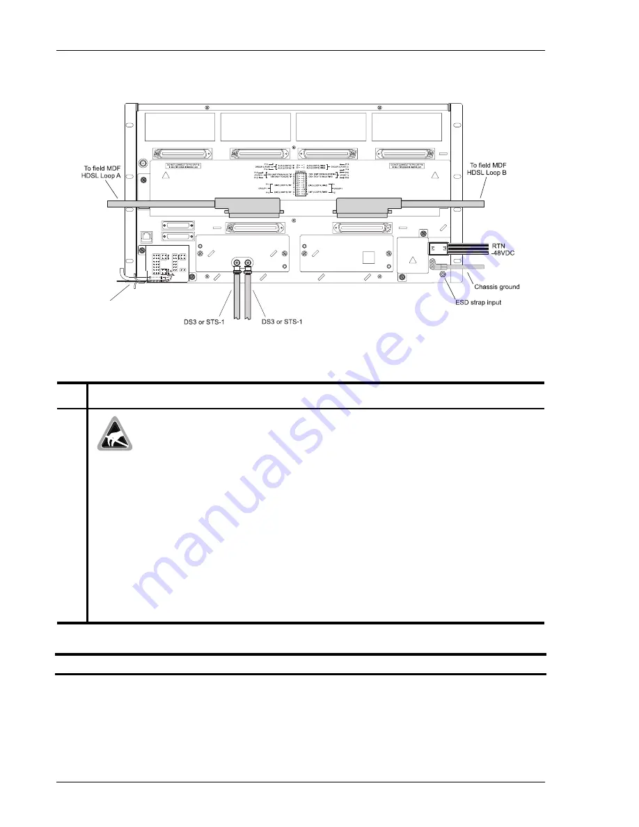
Figure 7.
Installing Cables for a DS3 or STS-1 Configured Shelf (Backplane View)
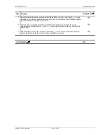
Step
Procedure
Installer Check
ü
Whenever installing or removing units from the HMS-358 chassis, be sure to wear an
antistatic wrist strap and connect it to the ESD strap input.
1
Connect the 32-pair shielded amphenol female connector to P11, HDSL LOOP A and route to the
field MDF.
See
“Drain Wire and Cable Tie Installation” on page 8
for proper installation of all amphenol
connectors.
H
2
Connect the 32-pair shielded amphenol female connector to P12, HDSL LOOP B and route to the
field MDF.
H
3
Connect a DS3 coaxial cable to Module A DS3 IN connector.
H
4
Connect a DS3 coaxial cable to Module A DS3 OUT connector.
H
5
“Wiring the Common Access Panel” on page 15
H
Installer Signature
?
Date
OUT
DS3
DS3
INPUT POWER: -48V, 30A MAX
10BaseT
33
1
MALE
64
32
33
1
64
32
32
64
MALE
1
33
32
64
MALE
1
33
32
64
1
33
32
64
1
33
MODULE B
MODULE A
FGND
RTN
-48VA
-48VB
RTN
10Base2 HMU
AUX RS-232 PORT
OS RS-232 PORT
10BaseT HMU
J32
J34
J30
J31
P11
P12
TB1
P14
DSX-1 (OUT) PORT 1
LOOP B GROUP 2
HDSL LOOP A GROUP 1 (XMT TO SPAN)
HDSL LOOP B GROUP 1 (RCV FROM SPAN)
DSX-1 (IN) PORT 1
LOOP A GROUP 2
P16
P13
P15
CAUTION:
VOLTAGES UP TO 200 VDC
MAY BE PRESENT
UNDER THIS COVER
UNDER THIS COVER
MAY BE PRESENT
VOLTAGES UP TO 200 VDC
CAUTION:
EXT
ACO
TX
RX
A+
NO
COM
CRT AUD
NC
COM NO
CRT VIS
MAJ AUD
MAJ VIS
MIN AUD
MIN VIS
SYS ID
TB2
TB5
SSC2
SSC3
SSC4
SSC5
SSC6
TB3
TB4
TEST ACCESS
BITS TIMING
SSC1
1
2
TIP
T
RING
R
R
T
TB7
FAN
DSX-1
TEST ACCESS
METALLIC
SHIELD
B-
B+
SHIELD
SHIELD
TB6
A-
OUT
IN
Alarms and test access

