LTPH-SM-1052-04
Wiring the Common Access Panel
HMS-358 List 5 and List 6
July 14, 2002
15
DSX-1
(O
pti
o
na
l Multiple
xe
r)
W
IRING
THE
C
OMMON
A
CCESS
P
ANEL
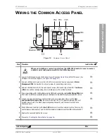
Figure 10.
Common Access Panel
Step
Procedure
Installer Check
ü
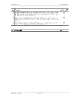
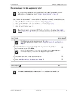
Whenever installing or removing units from the HMS-358 chassis, be sure to wear an
antistatic wrist strap and connect it to the ESD strap input.
1
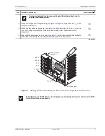
Loosen the hold-down lugs on the Common Access Panel (see
) and lift off the cover. (For
enlarged view of wire-wrap posts, see
H
2
Connect shielded alarm relay wires from the CO alarm center to the wire wrap posts at Alarm
Management (TB2). Follow the CO site instructions for connecting alarm relays.
H
3
Connect shielded transmit (TX) tip and ring and receive (RX) tip and ring at the DSX-1 Test Access
(TB3) block and the corresponding chassis shield posts to the external test head.
H
4
If you are installing an HXU-359 multiplexer in the HMS-358, connect the shielded Bits Timing (TB4) block
Bits A, Bits B, and the corresponding chassis shield posts to the SONET clock synchronization source.
H
5
If you have a requirement for an external alarm, such as an open door alarm, use the User
Configurable Alarm Inputs (TB5) block to wire the SSC1 EXT ACO (Special Signaling Channel 1
External Alarm Cutoff), the SSC2 (Special Signaling Channel 2), and the chassis shield to the
third-party alarm.
H
6
Wire COM pin and the NO pin of the Fan (TB7) block in series with an external rack fan. There is a dry
contact closure between pins 1 and 2 when the internal air temperature of the HMS-358 reaches 80°F.
H
7
Replace the cover and tighten the screws.
H
8
Proceed to
“Installing the Power Cables” on page 16
H
Installer Signature
?
Date
EXT
ACO
TX
RX
A+
NO
COM
CRT AUD
NC
COM NO
CRT VIS
MAJ AUD
MAJ VIS
MIN AUD
MIN VIS
SYS ID
TB2
TB5
SSC2
SSC3
SSC4
SSC5
SSC6
TB3
TB4
TEST ACCESS
BITS TIMING
SSC1
1
2
TIP
T
RING
R
R
T
TB7
FAN
DSX-1
TEST ACCESS
METALLIC
SHIELD
B-
B+
SHIELD
SHIELD
TB6
A-
OUT
IN
➀
➀
➀
➀
➁
➁
➂
➂
➃
➃
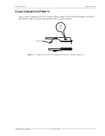
Shielded cable
TB2 TB3
TB4
TB5
TB6
TB7


