LTPH-SM-1052-04
Installing a Management Unit (HMU)
HMS-358 List 5 and List 6
July 14, 2002
25
I
NSTALLING
A
M
ANAGEMENT
U
NIT
(HMU)
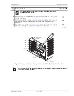
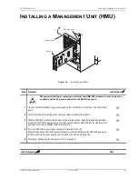
Figure 16.
Installing an HMU
Step
Procedure
Installer Check
ü
Whenever installing or removing units from the HMS-358 chassis, be sure to wear an
antistatic wrist strap and connect it to the ESD strap input.
1
Unscrew the two hold-down lugs on each upper corner of the chassis front cover. The cover folds
down.
H
2
Lift the retention bar at the top of the chassis to allow insertion of the module.
H
3
Hold the HMU-319 vertically with the front of the card toward you. Align the top and bottom edges
of the HMU-319 with the guide rails in the HMU slot and slide the HMU-319 into the rightmost slot
position on the chassis (labeled HMU). See
.
H
4
Press the HMU-319 firmly into the connector at the back of the slot.
When the pins on the HMU-319 connect to the pins on the shelf backplane, the HMU-319 powers up,
the Power LED lights green, and the Fail LED and Critical LED briefly flash red.
H
5
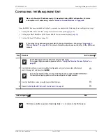
Proceed to
“Configuring the Management Unit” on page 29
H
Installer Signature
?
Date
xx
x
ESD strap input
HMU-319
HiGain MGT UNIT
HM
U-319
AC
O
A
L
M
MIN
OR
MA
JO
R
CR
ITIC
AL
EX
T C
OM
M
FA
IL
PO
W
ER
L
Retention bar

