LTPH-SM-1052-04
Installing
Multiplexers
HMS-358 List 5 and List 6
July 14, 2002
53
I
NSTALLING
A
L
INE
U
NIT
(HLU)
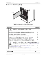
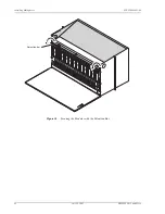
Figure 35.
Installing a Line Unit into the Wideband 3190 Chassis
Step
Procedure
Installer Check
ü
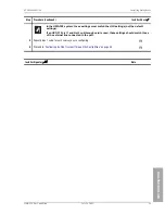
Whenever installing or removing units from the HMS-358 chassis, be sure to wear an
antistatic wrist strap and connect it to the ESD strap input.
1
Open the chassis front cover by unscrewing the two hold-down lugs on the upper corners. The cover
folds down.
H
2
Be sure to plug your ESD wrist strap into the ESD above the HMU slot.
H
3
Lift the retention bar at the top of the chassis to allow insertion of the module.
H
4
Slide the line unit into the card guides for the desired slot, then push the unit in until it touches the
backplane card-edge connector and the retaining latch on the front panel opens (
H
5
Place your thumbs on the line unit front panel and push the line unit into the card-edge connector until
it is entirely within the card guides and the retaining latch closes. This indicates that the card is properly
seated.
H
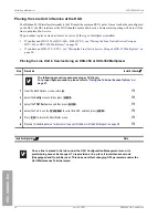
Do not enable alarms at this point in the procedure. You will not fully configure the HLU until the line
units are placed into service. This procedure is detailed in
“Placing the Line in Service” on page 57
.
6
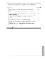
If you plan to install remote units, proceed to
“Installing a Remote Unit (HRU)” on page 55
, otherwise;
“Setting Up Circuit IDs” on page 56
H
7
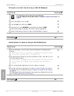
Pull down the retention bar to secure all the modules in the shelf (
H
Installer Signature
?
Date
HLU-319
E
strap input
SD

