LTPH-SM-1052-04
Appendix A - System Specifications
HMS-358 List 5 and List 6
July 14, 2002
75
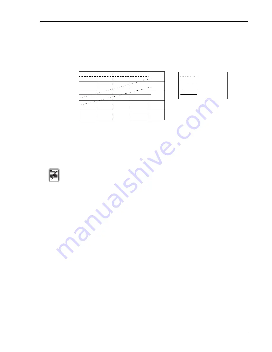
shows bay heat dissipation based on four chassis. Although the power requirements of the
system can vary greatly depending on the line makeup, in practice the line makeup seldom requires more than
30% of the lines to have doublers. With this type of provisioning, power limitations due to CO heating are seldom
a factor.
Figure 43.
Bay Heating Based on Doublers per Chassis
F
ANS
For a 0°C to 50°C (32°F to 122°F) operating environment, a fan assembly is required for any of these situations:
•
One system with
≥
230W power dissipation
•
Four systems with
≥
948W power dissipation
•
Extended temperature operation (65°C or 149°F)
No shelf configuration should exceed a total power dissipation
≥
1275W.
Each HDSL2 line must be counted as one doubler when using
to calculate heat
dissipation.
Bay Heating (4 Chassis)
400
600
800
1000
1200
1400
W
A
TTS
Total Number of
Doublers per Chassis
0
40
20
60
Fan Limit
Maximum
Bay Limit
Typical
80
100


