LTPH-SM-1052-04
Installing the Power Cables
HMS-358 List 5 and List 6
July 14, 2002
17
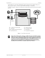
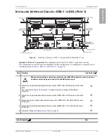
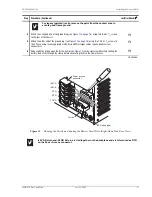
Figure 12.
Opening the Ferrite and Routing the Battery Feed Wires (Right-Hand Side, Rear View)
For legacy (painted) racks, remove the paint from the contact area to
ensure good frame ground.
3
Attach the L-shaped end of the ground lug (see
) using two 8-32 x
3
/
16
screws
to the rear of the chassis.
H
4
Attach the other end of the ground lug (see
) using two 12-24 x
1
/
2
screws to
the CO rack using locally approved methods (6 AWG or larger cables require double screw
connectors).
H
5
Reduce EMI by prying open the ferrite clamp (see
) with a slot screwdriver and routing the
battery feed wires through the clamp before connecting them to the Power Access.
H
Continued
-48 VA Return and -48 VB Return are tied together on the backplane and are referenced as RTN
on the Power Access connector.
Step
Procedure (Continued)
Installer Check
ü
Ferrite
-48 VA
-48 VB
RTN
RTN
FGND
Power access
connector
ESD strap input

