Installing the Power Cables
LTPH-SM-1052-04
18
July 14, 2002
HMS-358 List 5 and List 6
Step
Procedure (Continued)
Installer Check
ü
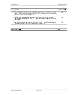
All connections to terminal block TB1 Power Access connector must be done to local
codes.
6
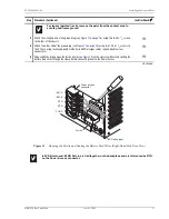
Attach a ring connector (or locally approved connector) to terminate the 12 AWG ground wire at
frame ground (FGND) on the Power Access connector (if needed).
H
7
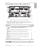
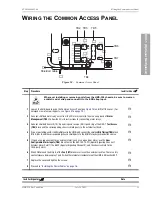
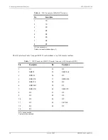
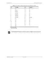
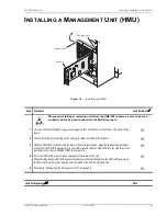
Connect a 12 AWG gauge wire to the -48 V RTN terminal in position 3 (see
) of
the Power Access connector. Connect the opposite end of this wire to the battery return of the CO
battery supply at the fuse panel. If a connector is required, conform to local code.
H
8
Connect a 12 AWG gauge wire to the -48 V RTN terminal in position 4 (see
) of
the Power Access connector. Connect the opposite end of this wire to the battery return of the CO
battery supply at the fuse panel. If a connector is required, conform to local code.
H
9
Connect a 12 AWG gauge wire to the -48 VA terminal in position 1 (see
) of the
Power Access connector (for slots 1-14). Connect the opposite end of this wire to the -48 Vdc CO
battery supply at the fuse panel. (Fuse is removed.) If a connector is required, conform to local code.
H
10
Connect a 12 AWG gauge wire to the -48 VB terminal in position 2 (see
) on the
Power Access connector (for slots 15-28). Connect the opposite end of this wire to the -48 Vdc CO
battery supply at the fuse panel. (Fuse is removed.)
H
11
Install a fuse of appropriate value in the fuse panel tray, based on the power recommendations given
in
“Power Specifications” on page 71
and
H
12
Close the ferrite clamp.
H
13
Connect the fuse panel to the office power supply according to CO guidelines.
H
14
With a voltmeter, verify voltages on the Power Access connector (see
There should be -48 Vdc across pins 1, -48 VA and RTNs 3 and 4 and pin 2, -48 VB and RTNs 3 and
4. Returns are tied together.
H
15
Replace the slide panel that covers the Power Access connector by placing the cover over the screws
and aligning the panel holes with the screws. Slide the panel
1
/
4
-inch to the right until it snaps into
place, then tighten the screws.
H
16
Proceed to
“Connecting the Network Interface” on page 19
H
Installer Signature
?
Date

