Installing Multiplexers
LTPH-SM-1052-04
42
July 14, 2002
HMS-358 List 5 and List 6
HXU-3
5
9
I
NSTALLING
THE
HXU-359 M
ULTIPLEXER
C
ARD
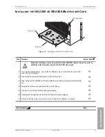
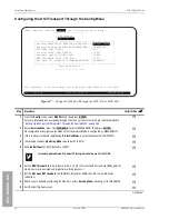
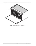
Figure 28.
Installing an HXU-359
Step
Procedure
Installer Check
ü
Whenever installing or removing units from the HMS-359 chassis, be sure to wear an
antistatic wrist strap and connect it to the ESD strap input.
1
Unscrew the two hold-down lugs on each side of the chassis front cover. The cover folds down.
H
2
Plug your ESD strap into the ESD input on the front of the chassis.
H
3
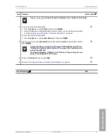
For an HMU-managed Wideband 3190, verify that switches 3 and 5 on the SW2 switch block located
on the circuit board are set to the OFF position (default). Switch 3 (OFF) activates the (Open Span
Termination System (OSTS) protocol for the backplane. Switch 5 (OFF) activates the HMU craft port
for management. All other positions should be off. (ON position is towards the front panel. OFF
position is towards the card-edge connector.)
H
The HXU-359 default dip switch settings are set for Wideband 3190 operation and should
not be modified.
4
Align the edges of the HXU-359 with the slot guides in the multiplexer tray.
H
5
Grasping the card eject tabs, gently push the card into the bay.
H
6
Firmly press in on the tabs until the card snaps into place.The LEDs flash momentarily. The Power
LED and Active LED on the active multiplexer remain illuminated. The LEDs on the inactive (standby)
multiplexer should be off, except for the Power LED.
H
7
Repeat
through Step 6 for the other HXU-359.
H
8
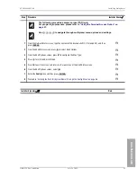
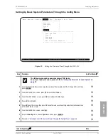
Proceed to
“Setting Up Basic System Parameters Through the Config Menu” on page 43
.
H
Installer Signature
?
Date
MUX card
ESD strap
input
Card eject tab
1
2
3
4
5
6
OFF ON

