Appendix A - System Specifications
LTPH-SM-1052-04
72
July 14, 2002
HMS-358 List 5 and List 6
P
OWER
R
EQUIREMENTS
Each system must be individually fused to support redundant power feeds. The HMS-358 List 5 provides a
split-power backplane to limit the current requirements of each battery feed line to less than 20A for any
configuration. The HMS-358 List 6 provides a diode-ORed feed that requires system configurations that are
limited to 20A per feed. For this reason, each battery feed line must be individually fused. However, fuse
requirements may be as low as 5A per fuse, depending upon the system configuration.
The power requirement for the shelf is characterized by three different measurements:
•
Current draw is the actual current drawn from the -48 Vdc Office Battery by the system. This is useful in
setting the requirements for shelf fusing. It is the total power consumption divided by the lowest office battery
voltage anticipated (-42.5 Vdc).
•
Power consumption is the total power used by the system and including the power fed to the remote
locations.
•
Power dissipation is that part of the total power that is consumed by the CO end of the system. It represents
the CO heating and is useful in calculating the power density (watts per square foot) for CO equipment.
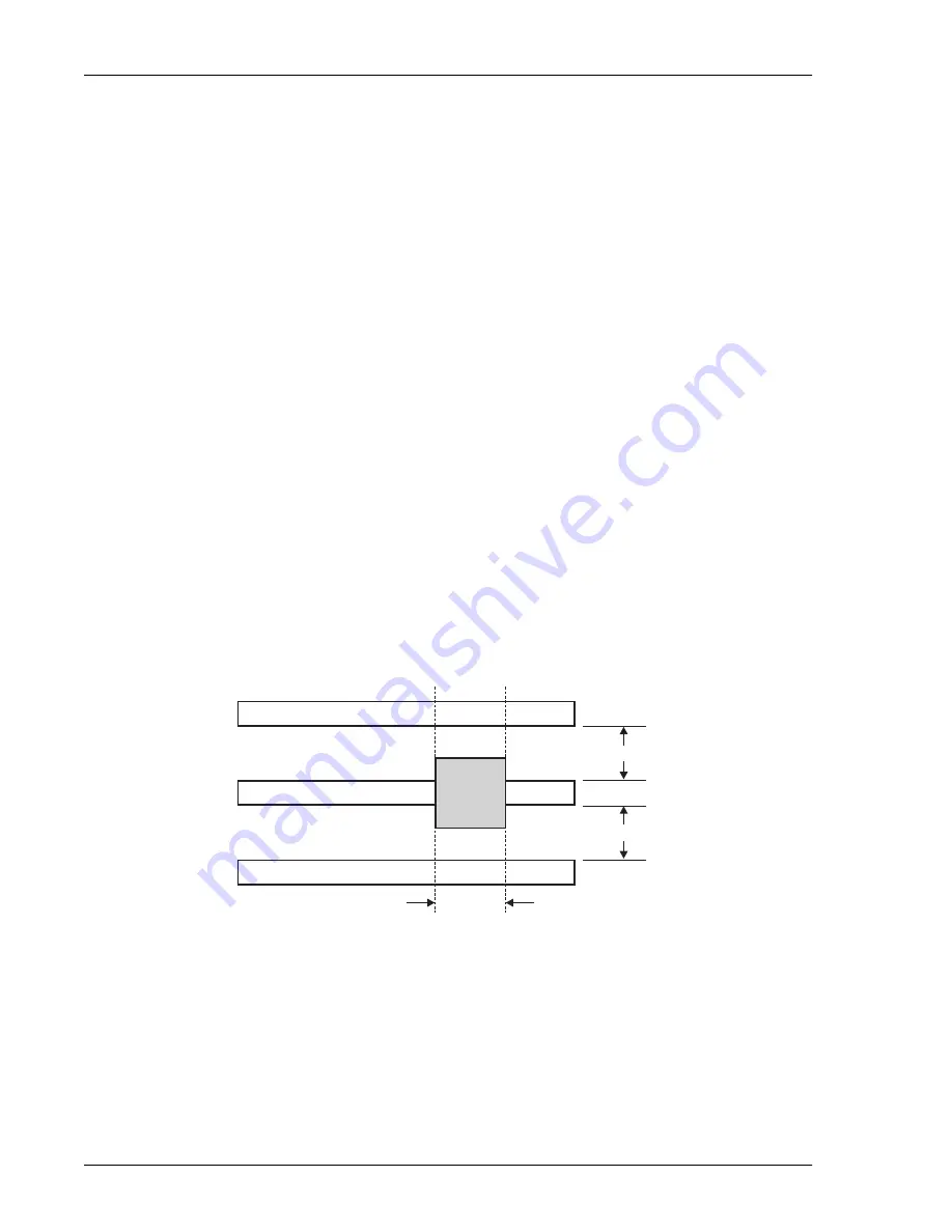
The requirements in GR-63-CORE for a typical six-lineup floor plan (
) of 12-inch deep frames (305 mm)
places the natural convection heat dissipation at 1450 W/m
2
(134.7 W/ft
2
). This is increased to 1950 W/m
2
if
forced-air fans are used.
Each 23-inch (584m) rack occupies 0.654m
2
(7.03 Ft
2
) of floor space. This allows 948W per rack without the
optional fan assembly and 1275W with the fan assembly.
For a maximum load, each rack should contain no more than four HMS-358s. Higher rack densities can be
obtained by installing the optional fan assembly in each system, by limiting the number of line doublers in each
system, or by changing the floor lineup of the racks.
The Wideband 3190 has been designed to provide adequate convection cooling for an environment of 0°C to 50°C
(32°F to 122°F) with up to 230W of internal heat dissipation.
Figure 42.
Typical Six-Lineup Floor Plan
Equipment frame lineup
Maintenance aisle
Wiring aisle
Rack
floor
area
660 mm
(2’2“)
762 mm (2’6“)
610 mm (2’)

