Appendix B - HMU Configuration for X.25 and Ethernet Connections
LTPH-SM-1052-04
78
July 14, 2002
HMS-358 List 5 and List 6
X.25 Parameter Configuration
The X.25 implementation of the HMU uses a fixed packet size of 128 bytes and cannot be changed. The HMU
does not support X.25 packet size negotiations.
By default, the HMU supports two Permanent Virtual Circuits (PVCs) and eighteen Switched Virtual Circuits
(SVCs). The HMU can be configured to support a specific number of PVCs and SVCs, but these parameters
cannot be configured using TL1 commands. In order to configure the number of PVCs and SVCs, the user must
run TAO.
The following steps describe how to configure the number of PVCs and SVCs.
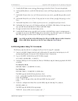
1
Connect to the HMU through a port configured for Interactive Mode. If connected to the Serial port, use a PC
running HyperTerminal; if connected to the Ethernet port, use a Telnet session.
2
Type TAO, then press
. If prompted for a password, type
public
, then press
. The Network
Status screen displays.
3
Type the number of the shelf to be configured. The Shelf Status screen displays
4
From the Shelf Status screen, press
to select X.25 Management.
5
From the X.25 Management screen, press
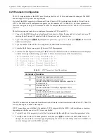
to select CUP Parameters. The CUP Parameters screen displays
with the following default settings (see
below for a description of the line indicators):
(A) B-Channel One 2-way Minimum LCI: 1
(B) B-Channel One 2-way Maximum LCI: 20
(C) Maximum Number of PVC Supported: 2
(D) PVC0 - Logical Channel Identifier: 1
(E) PVC1 - Logical Channel Identifier: 2
If no PVC connections are requested from the network, all twenty virtual circuits are available for SVC. The SVCs
are assigned Logical Channel 1 through 20.
If PVC connections are established, the number of SVCs supported by the HMU is either eighteen or nineteen,
depending on whether one or two PVCs were established.
6
To modify any of the parameters, select the line indicator (
through
), and enter the appropriate value.
7
Press
to return to the X.25 Management screen, then press
to return to the Shelf Status screen. If
changes have been made, a message appears prompting the user to save the changes and reset the HMU. To
save the changes and reset the HMU, press
.
Table 16.
CUP Parameters Line Descriptions
Line Indicators
Description
(A)
Information on logical channels and circuits.
(B)
Information on logical channels and circuits.
Indicates that the HMU is currently configured to support up to
20 virtual circuits.
(C)
Information on PVC.
Indicates that the HMU is currently configured for 2 PVCs.
(D)
Information on PVC.
Indicates that the first PVC is assigned Logical Channel 1
(E)
Information on PVC.
Indicates that the second PVC is assigned Logical Channel 2.
ENTER
ENTER
L
B
A
E
X
ESC
Y

