ADCP-80-526 • Issue 6 • December 2006
Page 10
© 2006, ADC Telecommunications, Inc.
1.16 Power-On Indicator
An optional visual power-on indicator (green LED) for each power bus is mounted near the
center of fuse platform front panel. If present, the LED, when lighted, indicates that power is
being applied to the bus input connectors. An unlighted LED indicates that power is not being
applied. The power-on indicator LED can be replaced in the field.
1.17 Fused Equipment Designation Card and Holder
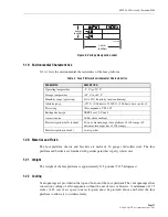
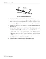
Two fuse designation cards, shown in
, and a card holder with a clear plastic cover are
provided with the fuse platform. The card holder may be attached to either the fuse platform, the
fuse platform mounting brackets, the rack, or a suitable surface close to the fuse platform. One
of the cards may be filled out with circuit information for each of the circuits and inserted in the
card holder. The card holder has a pressure-sensitive adhesive backing for attachment.
Additional fused equipment designation cards, card holders, and plastic covers can be ordered
separately if required.
Figure 4. Fuse Designation Cards
1.18 Voltage Designation Label
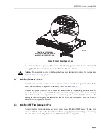
A voltage designation label, shown in
, is provided with the fuse platform. The label
may be filled out with the actual voltage present on the buses and placed on the fuse platform.
The voltage designation label has a pressure sensitive adhesive backing for attachment.
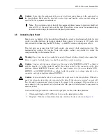
Note:
If a KLM or KTM fuse holder without a fuse is connected to a load, this situation
causes the red LED to light and the alarm contacts to change states, same as would occur
in a fuse failure. For other types of fuses (TPA and GMT), if a fuse holder without a fuse is
connected to a load, the corresponding sensor remains inactive and no failure is indicated.
18866-A
1.60 IN.
(4.06 CM)
2.36 IN.
(5.99 CM)
Summary of Contents for PowerWorx Power Distribution Products
Page 36: ...ADCP 80 526 Issue 6 December 2006 Page 30 2006 ADC Telecommunications Inc ...
Page 39: ......
Page 40: ...i www adc com ...


