7351 Series Digital Multimeter Operation Manual
6. HOW TO USE THE INTERFACE
6-1
6.
HOW TO USE THE INTERFACE
The 7351 series include the following standard interfaces according to the model.
7351A
USB and GPIB interfaces
7351E
USB interface
RS-232 interface (Option 03)
However, both interfaces cannot be used at the same time. Select either one.
6.1
Interface Selection
The interface can be selected and set only from MENU on the front panel.
1. Because the setting of the interface selection is saved in the nonvolatile memory, the setting does not
change even if the power is turned off or the interface is reset.
2. The address specific to the instrument is set in the interface. To identify each DMM on the USB inter-
face, the address of the USB interface (USB.ID) is set.
The address is displayed by turning on the power or using the address setting in MENU.
The interface setting item and the initial setting when shipping are shown below.
Setting item
Initial setting when shipping
Header ON/OFF
ON
GPIB address/USB.ID
1
GPIB talker function
Addressable
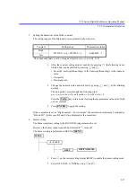
Select the interface from GPIB and USB in ‘BUS’ in
in
.
Press
to apply the setting.
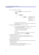
Header ON/OFF
Select ON or OFF in ‘HEADR’ in
in
.
Press
to apply the setting.
6.1.1
Response to the *IDN? Command
This instrument has changed its model name from “ADCE7351A/E” to “7351A/E.” Accordingly, the
response to the *IDN? command has also been changed. Note that an old model name response can also
be set to maintain the compatibility with the application software.
The new model name is set when the instrument is shipped.
A new or old model name response setting does not change by the initialization command or the factory
shipment initialization operation.
The new model name response to the *IDN? command is applied to software revision C00 or later.
8 I/F
MENU
ENTER
8 I/F
MENU
ENTER

