background image

7352 Series Digital Multimeter Operation Manual

4.2.1 Measurement Functions

4-10

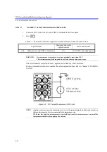
Figure 4-6    AC Voltage Measurement (ACV-Ach and ACV(AC+DC)-Ach)

Measurement method

TrueRMS

Input range

5% or more of a full scale

Crest factor

3 (This value is limited by the maximum allowable applied voltage.)

Filter response time

Approx. 1 sec (Time until the measurement value reaches to within
0.1% of the final value)

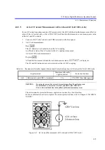
4.2.1.3

Ach Resistance Measurement (2W

-Ach and LP-2W

-Ach)

1. Connect a DUT to the 

 and COM terminals on the front panel.

2. Press .

Resistance is measured by using the two-wire method.

3. Re-press .

The LP indicator is activated to show the low power resistance measurement.
The resistance is measured in low power where the measurement current (IS) is reduced.

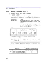
WARNING:

Do not apply voltage that exceeds the maximum allowable applied voltage. Fire or electrical
shock due to the failure of this instrument may occur.

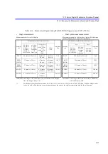
Table 4-3    Maximum Allowable Applied Voltage (ACV-Ach, ACV(AC+DC)-Ach)

Input terminal

Maximum allowable applied voltage

Ach

Between V

Hz and COM A terminals

1000 Vpeak, 700 Vrms, 2.2 

 10

7

 VHz

Between COM A terminal and the chassis

500 V

Between COM A and COM B terminals

200 V

500 V or less

1000 Vpeak

AC700 Vrms
2.2 

 10

7

 VHz

/LP-

/LP-

Summary of Contents for 7352A

Page 1: ...MANUAL NUMBER C Printed in Japan ADC CORPORATION All rights reserved 7352A E Digital Multimeter Operation Manual FOE 8440254B00 First printing August 10 2007 Applicable Models 7352A 7352E 2007 Cover...

Page 2: ......

Page 3: ...the provisions of the EMC Directive 2004 108 EC in accordance with EN61326 and Low Voltage Directive 2006 95 EC in accordance with EN61010 ADC Corp ROHDE SCHWARZ Japan Europe GmbH Munich Germany instr...

Page 4: ......

Page 5: ...3 8 3 4 2 Changing the Power Supply Voltage 3 9 3 4 3 Connecting the Power Cable 3 11 4 QUICK START 4 1 4 1 Panel Description 4 1 4 1 1 Front Panel Description 4 1 4 1 1 1 Display Section 4 2 4 1 1 2...

Page 6: ...igate the Menus 5 1 5 1 2 Menu List 5 4 5 2 Measurement Functions 5 8 5 2 1 Continuity Measurement 5 8 5 2 2 Temperature Measurement 5 8 5 3 Measurement Range and Auto Range 5 9 5 3 1 Measurement Func...

Page 7: ...6 3 2 RS 232 Setting 6 6 6 3 3 RS 232 Output Data Format 6 8 6 4 USB 6 9 6 4 1 Overview 6 9 6 4 2 USB Specifications 6 9 6 4 3 Setting Up the USB Port 6 9 6 4 3 1 Connecting to a Personal Computer 6 9...

Page 8: ...neral Specifications 7 17 7 4 Accessories 7 18 8 MAINTENANCE 8 1 8 1 Replacing Fuses 8 1 8 1 1 Replacing a Power Fuse 8 1 8 1 2 Replacing a Protection Fuse 8 2 8 1 2 1 How to Check Protection Fuses 8...

Page 9: ...7352 Series Digital Multimeter Operation Manual Table of Contents C 5 7352E DIMENSIONAL OUTLINE DRAWING EXT 2 ALPHABETICAL INDEX I 1...

Page 10: ......

Page 11: ...4 9 AC Current Measurement ACI Ach and ACI AC DC Ach 4 13 4 10 Continuity Measurement Ach 4 14 4 11 Diode Measurement Ach 4 15 4 12 Frequency Measurement FREQ Ach 4 17 4 13 DC Voltage Measurement DCV...

Page 12: ......

Page 13: ...h 4 19 4 13 Maximum Allowable Applied Current and Protection Function ACI Bch and ACI AC DC Bch 4 20 4 14 Maximum Allowable Applied Voltage TEMP 4 21 4 15 Measurement Speed during the HOLD OFF Trigger...

Page 14: ...eration Manual List of Tables No Title Page 8 1 Calibration Standards 8 6 8 2 Calibration Point 8 7 8 3 Parts with Limited Life 8 12 8 4 Before Asking for Repair 8 16 8 5 Initial Values of Setting Par...

Page 15: ...ter before using this instrument Chapter 3 SETUP This chapter describes how to setup this instru ment After setting up this instrument in an appro priate location turn on the power and check that this...

Page 16: ...d on the dual display Simple and easy panel operations with flexible and various system functions by using menus Large and visible fluorescent display Wide dynamic range Maximum display of 199999 on b...

Page 17: ...g the power cable Contact an ADC CORPORATION sales representative immediately 2 2 Removing the Case The case of this instrument should only be opened by ADC CORPORATION service engineers WARNING This...

Page 18: ...revented by the following precautions Changing the direction of the antenna of the television or radio Placing this instrument on the opposite side of the television or radio Placing this instrument a...

Page 19: ...or the cushioning material is damaged keep them until the following inspections are complete 2 Check that the outside of the product is not damaged WARNING If any outside components of the product su...

Page 20: ...10001 Each 1 Power Fuse For 100V 120V DFT AAR315A 1 1 2 Power Fuse For 220V 240V DFT AAR25A 1 Overcurrent protection fuse DFS AN2A 1 1 Operation manual E7352A E 1 This manual 1 The power cable include...

Page 21: ...e from corrosive gas An area away from direct sunlight A dust free area An area free from vibrations A low noise area Although this instrument has been designed to withstand a certain amount of noise...

Page 22: ...lectrostatic Countermeasures for the Work Floor and Human Body Figure 3 3 Electrostatic Countermeasures for the Workbench Table 3 2 ESD Countermeasures Human Body Use a wrist strap See Figure 3 2 Work...

Page 23: ...p The rating of the alligator clip adapter is 33 VAC and 70 VDC or less WARNING Must not touch the metal part of the input cable to prevent any damage of electrical shock Table 3 3 Accessories Name Mo...

Page 24: ...V measurements use the optional input cable A01001 in which the HI side is shielded The red wire of A01001 is shielded Do not cut the joint The rating of the probe decreases to 33 VAC and 70 VDC when...

Page 25: ...instrument or controller 3 Use shielded cables which are connected between peripherals Setting up the USB port To use the USB interface of this instrument the USB driver of the ADC instrument must be...

Page 26: ...ply voltage setting on the rear panel of this instrument is the same as the AC power supply voltage to be used Figure 3 4 Set Power Supply Voltage Indication Table 3 4 Power Supply Voltage Power suppl...

Page 27: ...fuse holder assembly by using flathead screwdrivers and then pull it out 2 Remove the power supply voltage selector from the fuse holder assembly 3 Rotate the power supply selector to be looked the c...

Page 28: ...s Digital Multimeter Operation Manual 3 4 2 Changing the Power Supply Voltage 3 10 5 Replace the fuse holder assembly into the rear panel 6 Check that the correct power supply voltage is indicated in...

Page 29: ...ver use a damaged power cable Doing so may cause an electrical shock 2 Connect the AC power connector on the rear panel of this instrument to a three pin power outlet that has a ground terminal by usi...

Page 30: ......

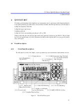
Page 31: ...er settings are set in the layered menus For more information on function descriptions and how to navigate the menus refer to Chapter 5 4 1 Panel Description 4 1 1 Front Panel Description The front pa...

Page 32: ...e measurement 2W in which the two wire method is used 2W and LP low power resistance measurement are alter nately switched by pressing this key while 2W is selected 4 DCI Ach Selects the Ach DC curren...

Page 33: ...ection Keys 1 AUTO Switches the measurement range between auto range and fixed range 2 DOWN Decreases the measurement range by one level and fixes the range 3 UP Increases the measurement range by one...

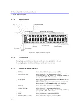
Page 34: ...this key again activates the left display section the first display and the 2nd indicator is turned off Since then opera tions while the 2nd indicator is off affect the left display 2 SHIFT 2nd The ri...

Page 35: ...4 5 4 1 1 12 CAT II Marking This display shows that the safety of this instrument satisfies the measurement category II which is com pliant with IEC 61010 1 Ed 2 Measurement category II is for measure...

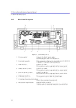
Page 36: ...or Connector for USB This connector is used to output data and for remote control 4 GPIB connector 7352A Connector for GPIB This connector is used to output data and for remote control 5 RS 232 connec...

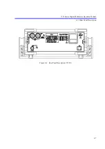
Page 37: ...7352 Series Digital Multimeter Operation Manual 4 1 2 Rear Panel Description 4 7 Figure 4 4 Rear Panel Description 7352E...

Page 38: ...ory defaults are used for descriptions in Chapter 4 For more information on how to initialize this instrument refer to Chapter 8 Depending on the measurement function the Bch indicator is turned on or...

Page 39: ...nel 2 ACV Ach measurement Press The AC indicator is activated to show the AC coupling An effective value of the AC voltage with AC coupling is measured ACV AC DC Ach measurement Re press ACV and DCV a...

Page 40: ...2 Press Resistance is measured by using the two wire method 3 Re press The LP indicator is activated to show the low power resistance measurement The resistance is measured in low power where the mea...

Page 41: ...n to ON before the mea surement Ensure the following when in the high resistance measurement to reduce the effect of the induction noise Shielding the DUT Using the A01001 input cable sold separately...

Page 42: ...the current protection fuse refer to Chapter 8 MAINTE NANCE Figure 4 8 DC Current Measurement DCI Ach NOTE Applying current causes the temperature to rise in the input terminals and internal circuits...

Page 43: ...he root mean square value is displayed The AC and DC indicators are activated to show the AC DC coupling WARNING Do not apply current that exceeds the maximum allowable applied current Do not measure...

Page 44: ...The resistance is measured using the two wire method If the measured value is equal to the continuity threshold constant or less the buzzer sounds Measurement range 2000 Measurement current 1 mA Cont...

Page 45: ...e between both terminals is measured Measurement range 2000 mV Measurement current 1 mA WARNING Do not apply voltage that exceeds the maximum allowable applied voltage Fire or electrical shock due to...

Page 46: ...the measurement is performed but the accuracy of the measured value may be out of the specifications Gate time NOTE When the sampling rate is set to SLOW the sampling rate indicator alternates between...

Page 47: ...7352 Series Digital Multimeter Operation Manual 4 2 1 Measurement Functions 4 17 Figure 4 12 Frequency Measurement FREQ Ach 500 V or less 1000 Vpeak AC700 Vrms 2 2 107 VHz...

Page 48: ...ge Fire or electrical shock due to the failure of this instrument may occur Figure 4 13 DC Voltage Measurement DCV Bch Table 4 10 Maximum Allowable Applied Voltage DCV Bch Input terminal Maximum allow...

Page 49: ...use refer to Chapter 8 MAINTE NANCE Figure 4 14 DC Current Measurement DCI Bch Restrictions on the auto range The 10 A range is a fixed range NOTE Applying current causes the temperature to rise in th...

Page 50: ...ean square value is displayed The Bch AC and DC indicators are activated to show the AC DC coupling WARNING Do not apply current that exceeds the maximum allowable applied current Do not measure a cur...

Page 51: ...surement Connect a thermocouple to the TEMP HI and LO terminals on the rear panel Press The C indicator is activated Temperatures at the terminals are internally compensated For the thermocouple selec...

Page 52: ...Measurement speed Measurement time Integration time Sampling rate Measurement speed Measurement time 1 Integration time DCV Ach DCV Bch DCI Ach DCI Bch 2W Ach LP 2W Ach ACV Ach ACI Ach ACI Bch Continu...

Page 53: ...h Continuity Ach Diode Ach DCV Bch DCI Bch ACI Bch FAST 80 times s 12 5 ms 45 times s 22 ms 38 times s 26 ms 2 ms FAST 64 5 times s 15 5 ms 2 ms MED 50 Hz 32 times s 31 ms 17 times s 58 ms 8 6 times s...

Page 54: ...h ACI Ach Continuity Ach Diode Ach DCV Bch DCI Bch ACI Bch FAST 74 times s 13 5 ms 42 times s 23 5 ms 38 times s 26 ms 2 ms FAST 60 times s 16 5 ms 2 ms MED 50 Hz 31 times s 32 ms 16 times s 60 ms 8 6...

Page 55: ...Ach DCI Bch 2W Ach LP 2W Ach ACV Ach ACI Ach ACI Bch Continuity Ach Diode Ach ACV AC DC Ach ACI AC DC Ach ACI AC DC Bch TEMP FREQ Ach Ach Bch DCV Ach DCI Ach 2W Ach LP 2W Ach ACV Ach ACI Ach Continui...

Page 56: ...s are for the second display right display 2 Select a function or calculation for the second display right display How to turn the second display right display off 1 Pressing on the front panel activa...

Page 57: ...e In cases where the Bch DC voltage DCV Bch is displayed on the left display and the Ach AC voltage AC DC coupling ACV AC DC Ach is displayed on the right display In cases where commands used in ADC C...

Page 58: ......

Page 59: ...Used to enter the values or select the setting Figure 5 1 Menu Operation 1 Press The Category layer in which to be selected is displayed 2 Select the category by using and Measured value display Note...

Page 60: ...l parameters For a numerical parameter set by entering a numerical value select either numer ical digit decimal point position or unit prefix by using and The operation of and varies depending on the...

Page 61: ...the Selection layer Moves to the Entry Execution layer Decreases the value Moves the target item to the left category Moves the target item to the left parameter Moves the target item to the numerica...

Page 62: ...calculation OFF ON MATH Other calculations OFF dB dBm SCL MAX MIN MAX MIN calculation and selecting the display OFF ON MAX MIN RESULT Display of the MAX MIN calculation result SAMPLE MAX MIN AVG PASS...

Page 63: ...VAL dB Constant D dB dBm 0 00001E 9 to 999999 E 6 P ON LD Selection of parameters which are loaded when the power is turned on P OFF USER0 SAVE Parameter save file selection USER0 USER1 USER2 USER3 LO...

Page 64: ...face NONE ODD EVEN STOP Stop bit selection Only when RS 232 is selected for the interface 1 BIT 2 BIT ECHO Echo selection Only when RS 232 is selected for the interface OFF ON HEADER Header OFF ON T O...

Page 65: ...Display and key tests F INHIB Disable function Each function can be set to ENA Enabling or DIS Disabling P LOCK Panel lock OFF ON PWD Password For panel lock 4 digits password CAL CAL mode OFF ON QUE...

Page 66: ...used in the measurement function 5 2 1 Continuity Measurement Setting the continuity threshold constant The continuity threshold constant can be selected in the range between 1 and 1000 from BEEP in...

Page 67: ...ACI AC DC Ach FREQ Ach Continuity Ach Diode Ach 2000 nA 20 A 200 mV 200 mV 200 200 200 A 200 A 200 mV 2000 mV 2000 mV 2000 2000 2000 A 2000 A 2000 mV 2000 2000 mV 20 V 20 V 20 k 20 k 20 mA 20 mA 20 V...

Page 68: ...value used when the range is changed Range DOWN When the displayed value is less than 10 of the displayed range less than 200 V if the DCV 1000 V range and 700 V range are both selected Range UP When...

Page 69: ...ed at the current measurement range in the measurement function and range shown in the following table Auto zero can be performed only once according to the measurement condition or measurement timing...

Page 70: ...ely 1 ms is required for the output to be displayed The time may vary depending on conditions Select OFF if sampling at high speed An error is displayed even if the display is set to OFF 5 6 Display D...

Page 71: ...ch measurement trigger note the life span of relays For more information refer to Section 8 4 Replacing Parts with Limited Life Because relays do not operate for the dual synchronous measurement using...

Page 72: ...F Ach Bch DCV ACV ACV AC DC LP DCI ACI ACI AC DC Continuity Diode FREQ DCV DCI ACI ACI AC DC TEMP Left side display Ach DCV Single measure ment Sequential measurement Two functions are alternately mea...

Page 73: ...ation Display section 1 The left display shows the state of the DCV function DCV Ach measured value 2 Press DCV Ach measured value 2nd 3 Press The set function is displayed on the right side display s...

Page 74: ...nt Trigger Measurement for the left side display Changing the function and range Measurement for the right side display Calculation Data output Measurement for the left side display Changing the funct...

Page 75: ...et function is displayed on the right side display section In this case the DCI Bch function is displayed DCV Ach measured value DCI Bch measured value 2nd SHIFT DCI Trigger Measurement for the left s...

Page 76: ...352A only INIT or INIT CONT ON TRIGger COUNt Terminate INIT CONT ON SAMPle COUNt Terminate Detecting the event start Waiting for TRIGger DELay For the single measurement Device action for the left sid...

Page 77: ...operation starts The IDLE state is changed to the INITiate state by using either of the following trigger system com mands Starting the trigger system INITiate Setting CONTinuous to ON INITiate CONTin...

Page 78: ...the TRG command or the GET command for GPIB is received from the enabled remote interface bus The following shows the parameters whose settings automatically change depending on the trigger source set...

Page 79: ...and left displays see Figure 5 6 b To activate each trigger delay for the right and left displays set T D EACH to ON in of If set to OFF it is disabled Set the trigger delay time for the second displ...

Page 80: ...n to the right and left displays Trigger input Measurement for the left side display Ach Measurement for the right side display Bch Calculation Data output Calculation Data output a Operation of the c...

Page 81: ...culates C dB calculation Calculates 20 log10 dBm calculation Calculates 10 log10 Comparator calculation Performs a comparative calculation HI GO LO MAX MIN calculation Calculates the maximum minimum a...

Page 82: ...depend on the current measurement range Example DC voltage measurement measurement range 2000 mV input voltage 1 V Measurement value 1000 00 mV Calculation Result 1 00000 V 3 If a calculation is perfo...

Page 83: ...ant The NULL calculation cannot be performed when the overload OL occurs The NULL constant can be checked in during the calculation The setting ranges are shown below The exponential part is set by us...

Page 84: ...thod the dispersion of those measurement values becomes small The smoothing calculation equation is shown below Pressing performs the calculation and the SM indicator in the display section turns on c...

Page 85: ...e smoothing calculation is canceled when any of the following conditions occur The key is pressed while the smoothing calculation is performed The measurement function is changed The RST command is ex...

Page 86: ...ation is performed Remember that any hazardous voltage present on the input connector or test lead may not detected at this time 2 Setting scaling constants NOTE Press the key if quitting the setting...

Page 87: ...al ing constant 3 Press to apply the setting 4 S OL scaling over S OL is displayed if the scaling calculation result exceeds the values of 999 999E 6 In this time the measurement range is not changed...

Page 88: ...he MATH item in the dB indicator in the display section turns on and the calculation is performed CAUTION The actual measured value is not displayed while the dB or dBm calculation is performed Rememb...

Page 89: ...llowing order n m No unit prefix k M Press the key in this mode if setting the measured value as Constant D 4 Press to apply the setting 3 Canceling the dB and dBm calculations The dB and dBm calculat...

Page 90: ...n MAX MIN calculation is set to ON the comparator calculation is applied to the value before the MAX MIN calculation 2 Setting the judgment conditions The setting examples of the High constant Low con...

Page 91: ...f The buzzer setting is performed in BEEP in 1 Press on the current setting display BEEP to enable the buzzer setting mode 2 Select OFF FAIL or PASS by using and 5 PASS condition setting In the PASS c...

Page 92: ...ing the measurement range and comparator operation The comparator function operates continuously even if the measurement range is changed The reference values for the judgment are not changed because...

Page 93: ...r sounds when the MAX or MIN value is renewed However although the displayed value is not changed the buzzer may sound This is because the resolution of measured value is higher than the resolution of...

Page 94: ...t Select a display item according to 2 Setting the calculation in this section The selected value is displayed by pressing 5 Canceling the MAX MIN calculation The MAX MIN calculation is canceled when...

Page 95: ...a to be calculated Average value SAVE Dispersion SPTP SMAX SMIN Standard deviation S 3 All measured data except for overload OL and calculation error data can be used for the calculation 2 Performing...

Page 96: ...if it is set to the auto range Auto range is determined according to the measurement value acquired before the cal culation is performed 3 Canceling the calculation between 2 measurements The calcula...

Page 97: ...conditions stored in USER0 can be loaded when the power is turned on Select from the followings in P ON LD in the category in P OFF Starts this instrument under the measurement conditions stored when...

Page 98: ...reaches 20 000 the buzzer which is set to ON sounds and the ST indicator blinks For the dual display use 10 000 in place of 20 000 5 11 2 Memory Recall Enter a data number to be recalled at RECALL in...

Page 99: ...om being selected because of malfunctions and to use this instrument safely some functions can be disabled Select each function to be set to ENA or DIS from F INHIB in the cat egory of Press to enter...

Page 100: ...the set function Diode Ach ACV AC DC Ach ACI AC DC Ach Continuity Ach ACI Ach FREQ Ach DCV Ach ACV Ach DCI Ach ACI Ach 2W Ach LP 2W Ach FREQ Ach Set function Function that depends on the set function...

Page 101: ...ng procedure Operation Display section 1 Press and select by using and MENU SYSTEM 2 Press SYSTEM BEEP 3 Select PWD by using and SYSTEM PWD 4 Press PWDnew 5 Select the digit in the numerical value ent...

Page 102: ...Select P LOCK by using and SYSTEM P LOCK 4 Press P LOCK OFF 5 Select ON by using and and press P LOCK ON 6 Select the digit in the numerical value entry section by using and Change the numerical value...

Page 103: ...command Up to 20 errors can be recorded For more information on error numbers and solutions refer to Section 8 11 Error Message List Reading the error queue Errors are displayed in order by pressing i...

Page 104: ......

Page 105: ...n if the power is turned off or the interface is reset 2 The address specific to the instrument is set in the interface To identify each DMM on the USB inter face the address of the USB interface USB...

Page 106: ...are common to the USB commands General Specifications Standard IEEE 488 Code ASCII code Logical level Logic 0 High state 2 4 V or more Logic 1 Low state 0 4 V or less Table 6 2 Interface Functions Cod...

Page 107: ...on the bus before connecting or disconnecting GPIB cables Check that the chas sis of the devices on the bus are connected to each other and to the ground before connecting or dis connecting any GPIB c...

Page 108: ...1 Select the following from T ONLY of in ON Talk Only OFF Addressable 2 Press to apply the setting Command language selection 1 Select the following from LANG of in ADC Command used in ADC CORPORATION...

Page 109: ...the rear panel of this instrument Up to 251 characters in one transmission can be recognized as a program code If a program code exceeds 251 characters an error occurs If the DSR data set ready statu...

Page 110: ...nguage selection 1 Select the following from LANG of in ADC Command used in ADC CORPORATION R6452 Command used in ADC CORPORATION s R6452 2 Press to apply the setting Baud rate 1 Select the following...

Page 111: ...2 Setting 6 7 2 Press to apply the setting Number of stop bits 1 Select the following from STOP of in 1 BIT 2 BIT 2 Press to apply the setting Echo 1 Select the following from ECHO of in ON OFF 2 Pres...

Page 112: ...put followed by a prompt and delimiter CR LF The following two prompts are used 3 Measured data output For the Only mode For the Only mode the measured data is output only if the RS 232 transmission i...

Page 113: ...from 1 to 127 can be set as USBid Remote Local Function is available Input command ASCII strings command which sets functions and the query command Output format ASCII strings which describe measureme...

Page 114: ...strument can be triggered by inputting a negative logic pulse from the external trigger terminal TRIG GER IN on the rear panel Select EXTernal as the trigger source when using this terminal Input the...

Page 115: ...er the selection layer 2 Select the LANG parameter by pressing and and press to enter in the entry layer 3 Select from ADC SCPI and R6452 by pressing and and press to apply the setting ADC Command use...

Page 116: ...s specified the command can be used but the oper ation in this instrument is as follow the 10 A range of the Bch current measurement function is set Command enabled only when R6452 is selected Trigger...

Page 117: ...ry output format With header and output data element Without header and output data element 1 Main header of 3 characters and sub header 2 S Space 3 Mantissa Polarity decimal point and 6 digit number...

Page 118: ...I AC current measurement ACI ACI AC voltage AC DC coupling measurement ACV AC DC ADV AC current AC DC coupling measurement ACI AC DC ADI Diode measurement DIODE DOD Low power 2W LP 2W R2L Continuity t...

Page 119: ...onresult information Comparator result HIGH H 3 GO P 3 LOW L 3 Calculation between 2 measurements Only 2nd display side D 3 MAX data M 4 MIN data I 4 AVE data A 4 dB data B 5 dBm data W 5 Scaling calc...

Page 120: ...asurements 9 99999E 35 DCV Ach 200 mV ddd dddE 03 2000 mV dddd ddE 03 20 V dd ddddE 00 200 V ddd dddE 00 1000 V dddd ddE 00 DCV Bch 200 mV ddd dddE 03 2000 mV dddd ddE 03 20 V dd ddddE 00 200 V ddd dd...

Page 121: ...E 00 ACI AC DC Ach 200 A ddd dddE 06 2000 A dddd ddE 06 20 mA dd ddddE 03 200 mA ddd dddE 03 2000 mA dddd ddE 03 FREQ Ach 10 Hz d dddddE 00 100 Hz dd ddddE 00 1000 Hz ddd dddE 00 10 kHz d dddddE 03 10...

Page 122: ...mmand set a wait time of 20 msec after the last command Item Command Description Valid command for the 2nd display setting Initial value R6452 Measure ment Function F1 DC voltage measurement DCV Ach F...

Page 123: ...Only RS 232 MD Measured data memory ST0 Store OFF ST1 Store ON ST Reply ST0 or ST1 IRDn m Sets the recall data range Single measurement mode n m 0 to 19999 Dual measurement mode n m 0 to 9999 If the...

Page 124: ...orcibly moves to the IDLE state Trigger source selection TRS0 IMMEDIATE TRS1 MANUAL TRS2 EXTERNAL 7352A TRS3 BUS TRS Reply TRS0 to TRS3 Trigger delay TRDn n 0 to 3600 seconds 2 0 TRD Reply TRD d ddddE...

Page 125: ...000 2000 mV R5 20 V 20 V 20 V 20 k 20 mA 20 mA 20 mA 20 k 20 V R6 200 V 200 V 200 V 200 k 200 mA 200 mA 200 mA 200 k 200 V R7 1000 V 700 V 700 V 2000 k 2000 mA 2000 mA 2000 mA 2000 k 700 V R8 20 M 20...

Page 126: ...E Reply One of RE3 to RE5 Auto zero AZ0 OFF AZ1 ON AZ2 ONCE Auto zero is set to OFF after this command is executed AZ Reply AZ0 or AZ1 Continuity threshold constant KOMn n 1 to 1000 setting resolution...

Page 127: ...1 ON SM Reply SM0 or SM1 TIn Smoothing count n 2 to 100 counts 10 TI Reply TIddd Scaling calculation SC0 OFF SC1 ON SC Reply SC0 or SC1 KAn Constant A Zero cannot be set n 999999 E 6 to 999999 E 6 Set...

Page 128: ...1 MAX Reads the MAX value 3 4 Reply M d dddddE dd MIN Reads the MIN value 3 4 Reply I d dddddE dd AVE Reads the AVE value 3 4 Reply A d dddddE dd AVN Reads the measurement count 3 Reply AVN d dddddE d...

Page 129: ...9 NOTE 1 If the recall data does not exist within the set range an error occurs 2 Parameters cannot be omitted 0 1 SIRD Reads the statistical calculation range Reply SIRDdddd dddd Initial state SIRD00...

Page 130: ...play NOTE Valid only when the 2nd display is ON 0 MCL Reply MCLd System 2nd display DE0 2nd display OFF DE1 2nd display ON DE Reply DE0 or DE1 1st 2nd display selection 5 DSP1 Selects the 1st display...

Page 131: ...52x nnnnnnnnn mmm nnnnnnnnn Serial No mmm Revision No IDN or IDN Header H0 Header OFF H1 Header ON 1 H Reply H0 or H1 Output data element specification ODEn 0 ODE Reply ODEddd Block delimiter 6 DL0 CR...

Page 132: ...dddd QSR Reads the questionable event register QER Reply ddddd QSEn Sets the questionable event enable register QEER n 0 to 65535 QSE Reply ddddd OSR Reads the operation event register OER Reply ddddd...

Page 133: ...mode to ON CAL Reply CAL0 or CAL1 XOUT Cancels sets to OFF the calibration mode Does not write the calibration factor PCn Enters the STD value Displayed count value n 0 to 999999 XDTn Enters the STD...

Page 134: ...queues can be stored The error is output according to the FIFO system If more than 20 errors occur the last error is replaced with 350 Queue overflow Any errors after this are not saved If no error o...

Page 135: ...ter is a numeric type or a character string type it is enclosed in angle brackets If the parameter is optional it is enclosed in braces Optional items are delimited by and the multiple descriptions in...

Page 136: ...age measurement DCV VOLTage AC AC voltage measurement ACV RESistance Resistance measurement 2W CURRent DC DC current measurement DCI CURRent AC AC current measurement ACI VOLTage ACDC AC voltage AC DC...

Page 137: ...fer to 6 6 3 RS232 Output data format MEASure function 1 Performs the measurement operation once and reads the measured value For more information refer to 6 6 3 RS232 Output data format READ Initiali...

Page 138: ...BUS Trigger delay TRIGger DELay real MAXimum MINimum ch 2 real 0 to 3600 seconds 0 TRIGger DELay MAXimum MINimum ch 2 Reply d ddddE dd Each trigger delay for the right and left displays TRIGger DELay...

Page 139: ...table maximum value see the table on the next page Sampling rate SENSe function SRATe FAST MED SLOW SSLow 1 FAST FAST MED MED SLOW SLOW1 SSLow SLOW2 The setting is applied to all functions SENSe funct...

Page 140: ...00 A 2000 A 1 99999E 03 20 mA 20 mA 20 mA 1 99999E 02 200 mV 200 mV 200 mV 200 mA 200 mA 200 mA 200 mV 200 mV 1 99999E 01 2000 mV 2000 mV 2000 mV 2000 mA 2000 mA 2000 mA 2000 mV 2000 mV 1 99999E 00 10...

Page 141: ...thing ch Reply 1 or 0 CALCulate SMOothing POINts int MAXimum MINimum ch Smoothing count int 2 to 100 counts 10 CALCulate SMOothing POINts ch Reply ddd Scaling calculation CALCulate SCALing ON 1 OFF 0...

Page 142: ...ALCulate AVERage MAXimum ch MAX value reading Reply d dddddE dd CALCulate AVERage MINimum ch MIN value reading Reply d dddddE dd CALCulate AVERage AVERage ch AVE value reading Reply d dddddE dd CALCul...

Page 143: ...CALCulate STATistics COUNt ch Reads the number of samples Reply d dddddE dd CALCulate STATistics MAXimum ch Reads the maximum value Reply d dddddE dd CALCulate STATistics MINimum ch Reads the minimum...

Page 144: ...FF FAIL PASS OFF OFF FAIL The buzzer sounds when the comparator cal culation result is FAIL PASS The buzzer sounds when the comparator calculation result is PASS CALCulate LIMit BEEPer Reply OFF FAIL...

Page 145: ...ister Reply ddddd STATus OPERation ENABle Reply ddddd STATus QUEStionable EVENt ch Reads the questionable event register Reply ddddd STATus QUEStionable ENABle int ch Sets the questionable event enabl...

Page 146: ...Enclose the character strings by using Up to 50 characters one byte alphanumeric characters can be stored CALibration STRing Reply xxxxx xxx Setting parameter SAV int int 0 to 3 Saves the setting par...

Page 147: ...correspondent to each event Sometimes the changes are retained Once this register is set the setting value is kept until it is read by a query or cleared by CLS Data cannot be written into the event r...

Page 148: ...eries Digital Multimeter Operation Manual 6 6 5 Status Register Structure 6 44 The status register structure in this instrument is shown in Figure 6 2 and Figure 6 3 Figure 6 2 Status Register Structu...

Page 149: ...7352 Series Digital Multimeter Operation Manual 6 6 5 Status Register Structure 6 45 Figure 6 3 Status Register Structure 2 2 1st display 2nd display 1st display 2nd display...

Page 150: ...tructure This section describes the status byte register The status byte register structure is shown in Figure 6 4 Figure 6 4 Status Byte Register Structure This status byte register follows the statu...

Page 151: ...r Queue and no data has existed in Error Queue 3 QSB Questionable Summary Bit ON When any event of Questionable Event Register occurs and Questionable Event Register is set to 1 this bit is set to 1 i...

Page 152: ...and is executed Table 6 5 Standard Event Status Register ESR bit Name Description 0 OPC Operation Complete ON This bit is set to 1 when all operations are complete after receiving the OPC command 1 No...

Page 153: ...e Description 0 FL FAIL ON This bit is set to 1 when the comparator calculation result satisfies the FAIL conditions 1 PS PASS ON This bit is set to 1 when the comparator calculation result satisfies...

Page 154: ...1 when OL occurs in the voltage or diode measurement 1 Current Overload ON This bit is set to 1 when OL occurs in the current measurement 2 Not used Always 0 3 Not used Always 0 4 Temperature Overload...

Page 155: ...When the power is turned on When the STATus OPERation ENABle 0 command is executed When the OSE0 command is executed Table 6 8 Operation Event Register OER bit Name Description 0 Not used Always 0 1...

Page 156: ...ed for receiving the GPIB data DMM_ADR 1 GPIB address of the 7352A Call ibdev 0 DMM_ADR 0 T10s 1 0 dmm Initializes the GPIB I F Call ibconfig dmm IbcUnAddr 1 Sets the transmitting and receiving addres...

Page 157: ...used in ADC CORPORATION 6 53 Call ibwrt dmm SD2 vbLf Sets the output data to the right side display Call ibrd dmm dt Reads the measured data on the right side display Cells 2 1 Left dt 18 Substitutes...

Page 158: ...f Sets the measurement range for the left side display to 2 V Call ibwrt dmm DSP2 F2 vbLf Sets the measurement function for the right side display to ACV Call ibwrt dmm DSP2 R4 vbLf Sets the measureme...

Page 159: ...ands used in ADC CORPORATION 6 55 Call ibwrt dmm DSP2 IRO vbLf Data reading for the right side display Call ibrd dmm dt Reads the measured data on the right side display Cells 2 1 dt Substitutes the m...

Page 160: ...DMM_ADR 1 GPIB address of the 7352A Call ibdev 0 DMM_ADR 0 T10s 1 0 dmm Initializes the GPIB I F Call ibconfig dmm IbcUnAddr 1 Sets the transmitting and receiving addresses individually Call ibwrt dmm...

Page 161: ...s the measured data on the left side display Cells 1 1 Left dt 18 Substitutes the measured value on the left side display for a cell Call ibwrt dmm FORMAT READING MCHANNEL 1 vbLf Sets the output data...

Page 162: ...e left side display to DCV Call ibwrt dmm SENSE VOLTAGE DC RANGE 1 99999 1 vbLf Sets the measurement range for the left side display to 2 V Call ibwrt dmm SENSE VOLTAGE DC SRATE MED vbLf Sets the samp...

Page 163: ...asured value on the left side display for a variable Cells 1 1 dt Substitutes the measured value on the left side display for a cell Call ibwrt dmm TRACE NUMBER 0 9 2 vbLf Sets the recall data range f...

Page 164: ...umber of stop bits 1 InputLen 0 Reads all of the buffers when the Input property is used PortOpen True Opens the port InBufferCount 0 Clears the receiving buffer DTREnable True Enables DTR dt Space 20...

Page 165: ...ata from the receiving buffer If InStr prompt Then Checks whether is received Exit Do Exits Do While Loop End If End If Loop End Sub Private Sub rx_data dt As String dt_len As Integer Subroutine for r...

Page 166: ...for receiving the USB data Dim ret As Long Declares the variable of the driver return value myID 1 Sets USB ID to 1 ret ausb_start 10 USB initialization time out 10 seconds If ret OK Then If the USB i...

Page 167: ...OK Then MsgBox transmission error vbExclamation GoTo err_exit End If Exit Sub err_exit ret ausb_close DMM If ret OK Then MsgBox device CLOSE error vbExclamation End If ret ausb_end If ret OK Then MsgB...

Page 168: ......

Page 169: ...efficient ppm of reading digits C FAST MED SLOW1 2 FAST MED SLOW1 2 FAST MED SLOW1 2 Auto zero ON Auto zero OFF V Hz COM A 200 mV 199 99 199 999 10 V 1 V More than 1 G 0 012 4 0 012 6 0 012 6 15 0 85...

Page 170: ...012 6 15 0 85 15 2 2000 mV 1999 9 1999 99 100 V 10 V More than 1 G 0 011 2 0 011 5 0 011 2 15 0 2 15 1 5 20 V 19 999 19 9999 1 mV 100 V 10 M 1 0 015 2 0 015 5 0 015 5 20 0 25 20 1 5 200 V 199 99 199...

Page 171: ...ue in the same range ACV Ach Input terminal Range Maximum display Resolution Input impedance FAST MED SLOW1 2 FAST MED SLOW1 2 V Hz COM A 200 mV 199 99 199 999 10 V 1 V 1 M 2 140 pF or less 2000 mV 19...

Page 172: ...10 mV 700 V 749 749 9 1000 mV 100 mV Range Measurement accuracy 1 of reading digits 20 Hz 45 Hz 45 Hz 100 Hz 100 Hz 20 kHz 20 kHz 50 kHz 50 kHz 100 kHz 200 mV 0 38 14 0 11 14 0 1 14 0 25 15 0 7 24 200...

Page 173: ...0 1 10 A 0 02 2 0 02 5 0 02 5 20 0 25 20 1 5 2000 k 1999 9 1999 99 100 10 1 A 0 03 2 0 03 10 0 03 10 35 2 35 5 20 M 19 999 19 9999 1 k 100 100 nA 0 2 2 0 2 10 0 2 10 155 2 155 5 200 M 199 99 199 999 1...

Page 174: ...15 40 150 4 150 4 20 A 19 999 19 9999 1 nA 100 pA 0 1 7 0 1 7 0 1 5 100 1 100 1 6 200 A 199 99 199 999 10 nA 1 nA 102 or less 0 04 20 0 04 40 0 04 40 40 4 40 5 2000 A 1999 9 1999 99 100 nA 10 nA 0 04...

Page 175: ...re coefficient ppm of reading digits C FAST MED SLOW1 2 FAST MED SLOW1 2 FAST MED SLOW1 2 Auto zero ON Auto zero OFF A COM B 10 A 11 999 11 9999 1 mA 100 A 0 03 or less 0 2 2 0 2 7 0 2 5 200 0 6 200 3...

Page 176: ...AST MED SLOW1 2 mA COM A 200 A 199 99 199 999 10 nA 1 nA 102 or less 2000 A 1999 9 1999 99 100 nA 10 nA 20 mA 19 999 19 9999 1 A 100 nA 2 or less 200 mA 199 99 199 999 10 A 1 A 2000 mA 1999 9 1999 99...

Page 177: ...35 20 20 mA 0 4 20 0 3 20 0 3 10 200 mA 0 4 20 0 3 20 0 3 10 2000 mA 0 5 20 0 35 10 0 7 20 1 For sine wave input When RATE is set to FAST or MED the digit term is reduced to 1 10 of its specification...

Page 178: ...ge Maximum display Resolution Resistance between terminals A fuse resistance is included FAST MED SLOW1 2 FAST MED SLOW1 2 A COM B 10 A 11 999 11 9999 1 mA 100 A 0 03 or less Range Measurement accurac...

Page 179: ...error to the ACI AC DC Bch measurement FAST MED of reading 20 45 Hz 1 24 0 72 45 Hz 1 kHz 0 06 Maximum allowable applied current Input protection Fuse replacement Between A and COM B terminals 10 A P...

Page 180: ...al is restricted to the maximum allowable applied voltage Gate time Maximum allowable applied voltage Input terminal Measurement frequency range Measurement accuracy V Hz COMA 10 Hz 300 kHz 0 02 of re...

Page 181: ...etween TEMP HI LO and COM A terminals 200 Vpeak Between TEMP HI LO and COM B terminals 200 Vpeak Between TEMP HI and TEMP LO terminals 36 Vpeak Between TEMP HI LO terminal and the chassis 500 V Input...

Page 182: ...measurement function Input terminal Range Maximum display Resolution Measurement current Measurement accuracy 1 of reading digits Temperature coefficient ppm of reading digits C FAST MED SLOW1 2 FAST...

Page 183: ...e D dBm display value 10 log Measured value 2 D 10 3 D is a constant Set by the user Statistical calculation Number of samples Display value SAMPLE Number of measured values in the specified range of...

Page 184: ...onnector 24 pin Anphenol Interface functions SH1 AH1 T5 L4 SR1 RL1 PP0 DC1 DT1 C0 E2 Output format ASCII Addressing 31 kinds of talker listener addresses can be specified from the front panel EIA232 7...

Page 185: ...rload display OL Trigger function Internal Remote External trigger signal 7352A Power supply AC power supply 100 V 120 V 220 V 240 V Can be switched by user Specify the option when ordering Use a powe...

Page 186: ...tandard accessory A01001 Shielded cable 33 VAC and 70 VDC or less Alligator clip adapter CC015001 33 VAC and 70 VDC or less RS 232 cable A01265 Terminal adapter TR1111 JIS rack mount set A02263 A02264...

Page 187: ...according to the following proce dure CAUTION 1 To prevent fire and electrical shock replace with a fuse listed in Table 3 1 Never use an incompatible fuse and short circuit the fuse holder 2 Whether...

Page 188: ...eck that the fuse is not open This instrument can measure the resistance of the protection fuse by connecting the terminals as shown in Figure 8 1 a For the mA terminal Connect the mA and terminals Se...

Page 189: ...nd remove the fuse 2 Replace with a fuse which is compliant with the standard and listed in Table 3 1 and secure the fuse cap Figure 8 2 Input Terminal Protection Fuse A protection fuse for the A curr...

Page 190: ...is instrument 8 2 1 Cleaning the Outside Use a soft or damp cloth to clean this instrument NOTE 1 Do not allow water inside this instrument or lint on this instrument 2 Do not use an organic solvent s...

Page 191: ...Power supply Use an AC power supply in a voltage range listed in Table 3 4 and frequency of 50 Hz or 60 Hz 2 Environment Perform calibration in following conditions Temperature 23 3 C Relative Humidi...

Page 192: ...kHz sine wave 1400 ppm 10 mVrms 100 mVrms 1 kHz sine wave 1000 ppm 190 mVrms 700 Vrms 1 kHz sine wave 200 ppm Resistance 190 50 ppm 1 9 k 190 k 20 ppm 1 9 M 50 ppm 19 M 100 M 1000 ppm DC current 1 9...

Page 193: ...stru ment is calibrated when the calibration is performed in the DC voltage and AC voltage measurements 8 In the continuity and diode measurements no calibration is required because the instrument is...

Page 194: ...en 19 mA 200 mA Open 190 mA 2000 mA Open 1900 mA ACI Ach 200 A Open 10 A 1 kHz 19 A 1 kHz 190 A 1 kHz 2000 A Open 50 A 1 kHz 190 A 1 kHz 1900 A 1 kHz 20 mA Open 500 A 1 kHz 1900 A 1 kHz 19 mA 1 kHz 20...

Page 195: ...the calibration standard to the input terminal 5 Calibrate the full scale point in a function and range to be calibrated 6 Cancel the calibration mode Setting the calibration mode 1 Select ON from CA...

Page 196: ...calibrate them in the order of calibration point1 2 and 3 13 Input a voltage equivalent to the calibration point 14 Pressing the key displays the measured value as a setting value 15 Adjust the settin...

Page 197: ...nd keys are disabled in the calibration mode Only and can be selected in 2 Before turning off the power cancel the calibration mode Calibration data is stored in internal nonvolatile memory and writte...

Page 198: ...he following table Note that the life span may be shorter than that described depending on the operating environment frequency of use and storage environment MEMO The table shows the life spans of par...

Page 199: ...Not used Location Unit Component Polychlorinated biphenyls PCB containing capacitors Not used Mercury containing components Not used Batteries Not used Printed circuit boards Used Main frame MAIN Pri...

Page 200: ...sed Main frame Electronic components Photocoupler and logic IC Nickel and Nickel compounds Used Main frame Electronic components and mechanical parts Lead and Lead compounds Used Main frame BPL 034166...

Page 201: ...rtation When transporting this instrument use the packing materials used for the shipping of this instrument or equivalent materials thickness of carton case is 5 mm or more Packing procedure 1 Place...

Page 202: ...pending on the mea surement range Check that the input cable is correctly con nected to the current input terminals 2000 nA and 2000 mA ranges mA and COM A terminals 10 A range A and COM B terminals S...

Page 203: ...or Calibration When sending this instrument to ADC CORPORATION sales representative attach a tag that indicates the following information Your company name and address Name of the person in charge Ser...

Page 204: ...mation on how to initialize the parameters refer to Section 5 10 Sav ing and Loading the Measurement Condition Settings Initial value when shipping The following describes how to set all parameters ex...

Page 205: ...OFF Saved value Selecting USER0 3 OFF HIGH value 0 0 Saved value Selecting USER0 3 0 LOW value 0 0 Saved value Selecting USER0 3 0 MAX MIN calcula tion OFF OFF Saved value Selecting USER0 3 OFF Selec...

Page 206: ...ved value Parity None None Saved value Stop bits 1 1 Saved value Echo OFF OFF Saved value Talk only OFF OFF Saved value Header output ON ON Saved value Output data element OFF OFF Saved value Selectin...

Page 207: ...0 0 0 Status register SESER 0 0 2 Status register MEER 0 0 0 Status register SRER 0 0 2 Status register QER 0 0 0 0 Status register STB 0 0 0 0 Status register OER 0 0 0 0 Status register SESR 0 0 0...

Page 208: ...and The test items are shown in Table 8 6 Table 8 6 Self Test Items Item Can be performed from the Panel or by Remote Can be performed when the power is turned on ROM check sum RAM read write check Pa...

Page 209: ...peration Display section 1 Press and select by using and MENU SYSTEM 2 Press SYSTEM BEEP 3 Select P KEY by using SYSTEM P KEY 4 Press P KEY ENTER 5 Press All segments of the display are turned on The...

Page 210: ...air 13 Err 206 Ach Lx1 zero measurement test error in analog operation Repair 14 Err 207 Ach Lx10 zero measurement test error in analog operation Repair 15 Err 208 Ach Lx100 zero measurement test erro...

Page 211: ...cution error Command which cannot be executed now Execution error Solution6 41 Err 213 The INITiate command is ignored because the measurement is performing Init ignored Solution6 42 Err 214 The READ...

Page 212: ...ion Solution2 Check the USB cable connection Solution3 Calibrate according to the correct procedure Solution4 Perform the ZERO calibration Solution5 Send the correct command Solution6 Check the settin...

Page 213: ...ONAL OUTLINE DRAWING Unit mm NOTE This drawing shows external dimensions of this instrument The difference in products and options used can cause a change in the appearance of the instrument DIMENSION...

Page 214: ...7352E DIMENSIONAL OUTLINE DRAWING Unit mm NOTE This drawing shows external dimensions of this instrument The difference in products and options used can cause a change in the appearance of the instru...

Page 215: ...tion Functions 5 23 7 15 Calculation Selection Keys 4 3 Calibration 8 5 Calibration Point 8 7 Calibration Procedure 8 9 Calibration Standards 8 6 CAT II Marking 4 5 Caution when Connecting Peripherals...

Page 216: ...l Description 4 1 Power Fuse 2 1 Power Requirements 3 8 Power Switch 4 2 PRECAUTIONS 2 1 Precautions in Use of GPIB 6 3 Preparing for Calibration 8 5 Product Disposal and Recycle 8 13 Product Overview...

Page 217: ...oring and Recalling Measurement Data 5 40 System Recovery Procedure 8 18 System Settings 5 41 T Temperature Measurement 4 21 5 8 Temperature Measurement TEMP 7 13 Transportation 8 15 Trigger Count Set...

Page 218: ......

Reviews: