7352 Series Digital Multimeter Operation Manual
4.2.1 Measurement Functions
4-16
4.2.1.8
Ach Frequency Measurement (FREQ-Ach)
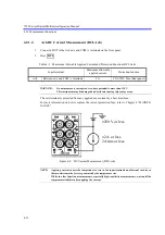
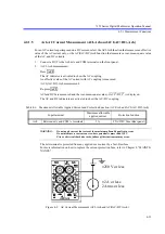
1. Connect a DUT to the Ach V and COM terminals on the front panel.
2. Press
and .
The frequency in the ACV-Ach measurement function is displayed.
The DC component of the input signal is cut by the AC coupling and the frequency is measured at the
zero-cross point.
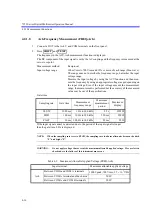
Measurement method
Reciprocal
Input voltage range
100 mVrms to 700 Vrms and 10% or more of each range (Sine-wave)
The range does not describe the frequency range, but rather the input
voltage range.
Measure the input voltage by using the ACV function and then mea-
sure the frequency by using an appropriate voltage range depending on
the input voltage. Even if the input voltage exceeds the measurement
range, the measurement is performed but the accuracy of the measured
value may be out of the specifications.
Gate time
NOTE:
When the sampling rate is set to SLOW, the sampling rate indicator alternates between the dark
“S” and bright “S”.
WARNING:
Do not apply voltage that exceeds the maximum allowable applied voltage. Fire or electric
shocks due to the failure of this instrument may occur.
Sampling rate
Gate time
Measurement
frequency range
Maximum
measurement
period
Maximum
display
SLOW
1000 ms
1 Hz to 300 kHz
2.2 s
999999
MED
100 ms
10 Hz to 300 kHz
220 ms
99999
FAST
10 ms 100 Hz to 300 kHz
22 ms
9999
If the input signal cannot be detected due to the period of the input signal is longer
than the gate time, 0 Hz is displayed.
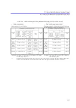
Table 4-9 Maximum Allowable Applied Voltage (FREQ-Ach)
Input terminal
Maximum allowable applied voltage
Ach
Between V
Hz and COM A terminals
1000 Vpeak, 700 Vrms, 2.2
10
7
VHz
Between COM A terminal and the chassis
500 V
Between COM A and COM B terminals
200 V
SHIFT
TEMP

