7451A/7461A/7461P Digital Multimeter Operation Manual
4.2.1 Measurement Functions
4-12
6. AC current measurement (ACI and ACI(AC+DC))
ACI measurement
1. Press .
AC current with AC coupling is measured.
2. Pressing
continuously switches the AC filter in turn.
ACI(AC+DC) measurement
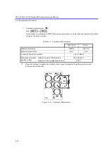
3. Press
and
.
ACI and DCI are measured and the root mean square value (
) is
displayed.
The AC and DC indicators are turned on to show the AC+DC coupling.
4. Pressing
continuously switches the AC filter in turn.
5. Press
and
to return to the ACI measurement.
Selecting the AC Filter
In this instrument, the AC filter can be selected from three for the accuracy optimization in low fre-
quency and the high speed response.
Select the AC filter in consideration of the measurement signal frequency, necessary measurement
accuracy, and response time.
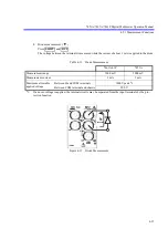
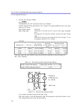
Maximum allowable applied current
3 A
WARNING:
Must not measure a current source whose voltage is more than 250 V.
This instrument may be damaged and injury or an accident may occur.
The mA terminal is protected from the applied overcurrent by using the fast-blow fuse.
For more information on how to replace the overcurrent protection fuse, refer to Chapter 8, “MAIN-
TENANCE.”
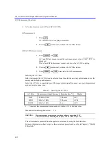
Table 4-9 Selecting the AC Filter
AC filter
Measurement signal frequency Response time *1
Display
FAST
300 Hz to 5 kHz
100 msec
ACF
MED
20 Hz to 5 kHz
500 msec
ACM
SLOW
20 Hz to 5 kHz
3 sec
ACS
*1:
Time until the measurement value reaches to within 0.1% of the final value
ACI
ACI
SHIFT
ACI
ACI
2
+DCI
2
ACI
SHIFT
ACI


