CHAPTER 4
Sensor Type Configuration
173
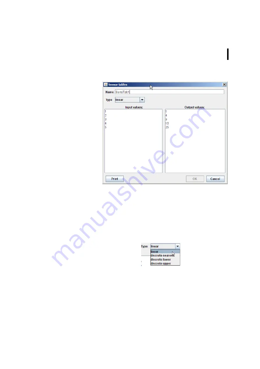
Figure 179. Sensor tables
The “Sensor tables” window provides the following window areas:
•
Name - allows you to enter a unique name for each
conversion table to be determined; later, in the Sensor Type
window, the conversion of the data of a sensor (also referred
to as “the linearization of a sensor”) can be performed under
this name;
•
Type - allows you to select the type of interpolation to be
used:
Figure 180. Type of Interpolation
•
linear - a linear interpolation is used, i.e. an intermediate
value is calculated according to the ratio of the distances
to the neighboring values contained in the table;
Summary of Contents for A850
Page 92: ...CHAPTER 3 Configuring the Gateway 92 Figure 81 PPP Configuration Window ...
Page 128: ...CHAPTER 3 Configuring the Gateway 128 Figure 132 Dialup Modem Window ...
Page 164: ...CHAPTER 3 Configuring the Gateway 164 ...
Page 177: ...CHAPTER 4 Sensor Type Configuration 177 Figure 183 Sensor type Window Analog ...
Page 196: ...CHAPTER 4 Using the Gateway 196 Figure 216 Sensor type Window LC ...
Page 200: ...CHAPTER 4 Using the Gateway 200 Figure 222 Sensor type Window OC ...
Page 204: ...CHAPTER 4 Using the Gateway 204 Figure 228 Sensor type Window SDI ...
Page 215: ...CHAPTER 4 Logs 215 Figure 241 System Log Selection Log types Figure 242 System Log Log types ...
Page 275: ...CHAPTER 4 RTU Network Configuration 275 Sensor details Figure 319 Sensor details Window ...
Page 366: ...CHAPTER 6 Appendix 366 ...


