CHAPTER 4
Using the Gateway
180
Figure 189. Sensor type - Analog sensor settings - Cabling
•
Sensor supply time - the delay allowed for the sensors to
settle after power has been applied to them (the default value
is 2 seconds) so that the sampling of accurate measurements
can begin.
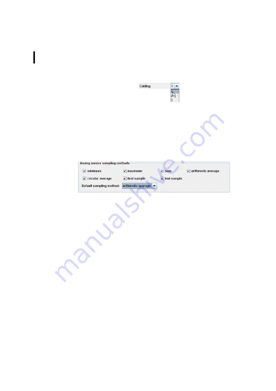
Analog sensor sampling methods
Figure 190. Sensor type - Analog sensor sampling methods
Determination of the sampling methods permitted for the sensor
type and selection of the sampling method to be used.
Allowed sampling methods - check all check boxes for sampling
methods that are allowed for this sensor type:
•
minimum - set sampling method to minimum, i.e. the
specified analog channel is instructed to store the lowest
sampled value;
•
maximum - set sampling method to maximum, i.e. the
specified analog channel is instructed to store the highest
sampled value;
•
sum - set sampling method to sum, i.e. the specified analog
channel is instructed to store the sum of all sampled values;
•
arithmetic average - set sampling method to arithmetic
average, i.e. the specified analog channel is instructed to
store the arithmetic average of all sampled values;
•
circular average - set sampling method to circular average, i.e.
the specified analog channel is instructed to store the circular
average of all sampled values;
Summary of Contents for A850
Page 92: ...CHAPTER 3 Configuring the Gateway 92 Figure 81 PPP Configuration Window ...
Page 128: ...CHAPTER 3 Configuring the Gateway 128 Figure 132 Dialup Modem Window ...
Page 164: ...CHAPTER 3 Configuring the Gateway 164 ...
Page 177: ...CHAPTER 4 Sensor Type Configuration 177 Figure 183 Sensor type Window Analog ...
Page 196: ...CHAPTER 4 Using the Gateway 196 Figure 216 Sensor type Window LC ...
Page 200: ...CHAPTER 4 Using the Gateway 200 Figure 222 Sensor type Window OC ...
Page 204: ...CHAPTER 4 Using the Gateway 204 Figure 228 Sensor type Window SDI ...
Page 215: ...CHAPTER 4 Logs 215 Figure 241 System Log Selection Log types Figure 242 System Log Log types ...
Page 275: ...CHAPTER 4 RTU Network Configuration 275 Sensor details Figure 319 Sensor details Window ...
Page 366: ...CHAPTER 6 Appendix 366 ...


