CHAPTER 4
RTU Network Configuration
245
Select destination RTU
•
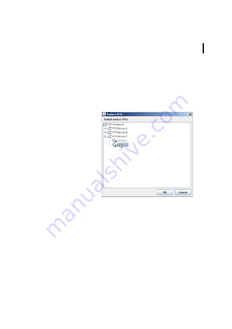
Select the destination RTU within your RTU network to be
replaced and then select “Replace RTU” in the RTU context
menu.
Select source RTU
Figure 278. Replace RTU Window
•
Select the source RTU within yor RTU network from which you
want the RTU information to be taken over;
•
after you gave a confirmation by clicking the OK button, the
information of the selected source RTU will be taken over to
the RTU selected in the tree window or in the table window
(
destination RTU
).
Note: By this, all the information within the destination RTU is
totally overwritten by the information from the source RTU.
Of course, source RTU and destination RTU have to be dif-
ferent from each other.
Summary of Contents for A850
Page 92: ...CHAPTER 3 Configuring the Gateway 92 Figure 81 PPP Configuration Window ...
Page 128: ...CHAPTER 3 Configuring the Gateway 128 Figure 132 Dialup Modem Window ...
Page 164: ...CHAPTER 3 Configuring the Gateway 164 ...
Page 177: ...CHAPTER 4 Sensor Type Configuration 177 Figure 183 Sensor type Window Analog ...
Page 196: ...CHAPTER 4 Using the Gateway 196 Figure 216 Sensor type Window LC ...
Page 200: ...CHAPTER 4 Using the Gateway 200 Figure 222 Sensor type Window OC ...
Page 204: ...CHAPTER 4 Using the Gateway 204 Figure 228 Sensor type Window SDI ...
Page 215: ...CHAPTER 4 Logs 215 Figure 241 System Log Selection Log types Figure 242 System Log Log types ...
Page 275: ...CHAPTER 4 RTU Network Configuration 275 Sensor details Figure 319 Sensor details Window ...
Page 366: ...CHAPTER 6 Appendix 366 ...


