CHAPTER 4
RTU Network Configuration
279
•
Sensor value - enter the minimum and maximum value of the
range within which the sensor delivers measurements;
Note: The default range of the sensor value ist defined in “Sensor
Type configuration” in the field “Linear input value”.
•
Physical value - enter the minimum und maximum of the
linear output value range which corresponds the linear input
values in the selected range.
Note: The default range of the physical value ist defined in “Sen-
sor Type configuration” in the field “Linear output value”.
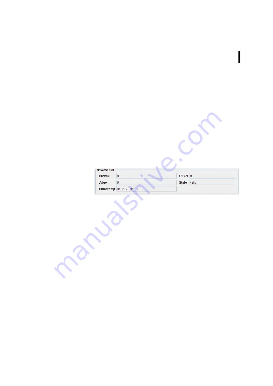
Newest slot
Figure 326. Sensor details - Newest slot
•
Interval - displays the measurement interval of the newest
slot;
•
Offset - displays the offset between save and measurement
timestamp of the newest slot;
•
Value - displays the measurement value of newest slot;
•
State - displays the state of newest slot value:
•
valid - valid and complete value;
•
partial - valid, but incomplete value (some samples
missing);
•
missing - missing value (all samples missing);
•
invalid - invalid (sensor or cabling problem).
•
Timestamp - displays the timestamp when the newest slot
was saved.
Summary of Contents for A850
Page 92: ...CHAPTER 3 Configuring the Gateway 92 Figure 81 PPP Configuration Window ...
Page 128: ...CHAPTER 3 Configuring the Gateway 128 Figure 132 Dialup Modem Window ...
Page 164: ...CHAPTER 3 Configuring the Gateway 164 ...
Page 177: ...CHAPTER 4 Sensor Type Configuration 177 Figure 183 Sensor type Window Analog ...
Page 196: ...CHAPTER 4 Using the Gateway 196 Figure 216 Sensor type Window LC ...
Page 200: ...CHAPTER 4 Using the Gateway 200 Figure 222 Sensor type Window OC ...
Page 204: ...CHAPTER 4 Using the Gateway 204 Figure 228 Sensor type Window SDI ...
Page 215: ...CHAPTER 4 Logs 215 Figure 241 System Log Selection Log types Figure 242 System Log Log types ...
Page 275: ...CHAPTER 4 RTU Network Configuration 275 Sensor details Figure 319 Sensor details Window ...
Page 366: ...CHAPTER 6 Appendix 366 ...


