20
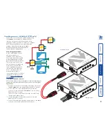
To zero the skew adjustment dials
When supplied, the two skew dials are set in
their neutral positions. i.e. no delay to either
of its colours. However, if the module has
been previously used and adjusted then you
may need to relocate the zero point. There are
no setting markers around the two skew dials
and the dial itself does not have a pointer.
1 Insert a small screwdriver into the skew
dial and twist it all the way anticlockwise.
Note the position of the dial when it
reaches its end point.
2 Rotate the screwdriver fully clockwise and
again note the endpoint position of the
dial.
3 Now rotate the screw driver anticlockwise until the dial reaches the position
that lies midway between the two end points. This is the neutral position.
4 Repeat this procedure for the other skew dial, if necessary.
0
(no compensation)
Max
Max
To adjust the skew compensation
Your chances of achieving a successful skew compensation adjustment will be
improved if you do the following:
• Ensure that you have a clear view of one or both display screens,
• Display a suitable RGB test pattern, either the
supplied pattern
or a
self-
created version
,
• Use a screwdriver of an appropriate size to adjust the dials,
• Begin with both skew dials in their neutral positions - if the module has
been previously used and skew adjusted for an alternative installation, zero
the dials as described in the section ‘To zero the skew adjustment dials’ left.
NOTE: AV200 receiver modules must be placed into skew compesation
mode - see opposite.
0
(no compensation)
Skew RG
Skew GB
0
(no compensation)
Delay
RED
Delay
GREEN
Delay
GREEN
Delay
BLUE
1 Turn the
SKEW RG
dial clockwise or anticlockwise until you observe that the
red and green colours are aligned.
2 Turn the
SKEW GB
dial clockwise or anticlockwise until you observe that the
green and blue colours are aligned.
3 Your actions in
step 2
may alter the Red/Green alignment. If so, go back to
the
SKEW RG
dial and turn it clockwise or anticlockwise until you observe
that the Red and Green colours are aligned, at which point all of the colours
will be aligned.
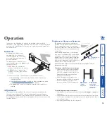
To place the AV200 receiver into skew compensation mode
NOTE: This procedure is not required for the AV101 receiver.
The AV200 receiver module shares one of its processors between the duties of
operating its serial port and adjusting the skew compensation. When power
is first applied to the module, it enters a neutral state for up to ten seconds
signified by a fast flickering red indicator. During this time, if you move one of
the skew dials, the module will enter skew mode.
1 Apply power to the AV200 receiver module. The red indicator should flicker
rapidly for up to ten seconds.
2 Using a small screwdriver, rotate one of the skew dials slightly. The
red indicator should flash slowly signifying that the module is now in
skew compensation mode. Continue to make your skew compensation
adjustments in the usual manner - see opposite.
3 Once the necessary adjustments have been made, remove power from the
module for a few seconds and then reapply. The module will automatically
settle into its default serial port mode after ten seconds.


