14
INST
ALLA
TION
CONFIGURA
TION
OPERA
TION
FUR
THER
INFORMA
TION
INDEX
Configuration
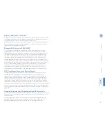
MODE SWITCH SETTINGS
The local module has two small switches on its rear panel. These are used to determine
which operation modes should be used. You will need to re-power the local module
whenever a switch setting is changed.
Switch B
Link mode
Determines the priority for the data link:
Longer distance or higher screen resolution.
UP
- Long reach mode - Limits the pixel clock (148.5MHz)
so that longer stretches of link cable (exceeding 100m) can be
used. This will restrict the achievable screen resolution to a
maximum of 1920 x 1080 at 60Hz (aka ‘1080P’).
DOWN
- High rate mode - Allows a higher pixel clock
(165MHz) to support screen resolutions of up to 1920 x
1200 at 60Hz (aka ‘WUXGA’). This will limit the maximum
link cable length to around 100m or less, depending on the
type of link cable used.
Note: When high rate mode is used, the modules will continually
check the link quality to ensure that it is capable of supporting
the higher pixel clock. If excessive data errors are detected, the
modules will fall back to Long Reach mode until the local module
is reset or the link is broken and re-established.
Switch A
USB compatibility mode
Determines whether USB compatibility
mode should be used.
UP
- Normal mode - Use this if the modules are not
connected to a KVM switch.
DOWN
- Compatibility mode - Use this if either
the local or remote modules are connected to a
KVM switch. This mode ensures robust and reliable
operation with KVM switches but also reduces the
maximum USB data rate.
Local module
rear panel
Note: The default position for both
switches is
UP
, thus selecting Long reach
mode and high speed (normal) USB mode.
Changes to the mode switches are
not recognized until you re-apply
power to the local module.
HT


