background image















6













Power connection

The rack drawer is provided with a power adapter capable of supplying the 
display monitor, keyboard and in-built KVM module. 

IMPORTANT: You must only use the manufacturer approved power adapter with 
the 

rack drawer

.

IMPORTANT: Due to the length of the power cable, if the rack drawer is 
mounted high in the rack it may not be possible to place the power adapter at 
floor level. In this case it is important to mount it securely and in such a manner 
that it is not suspended from its output cable.

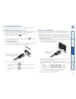
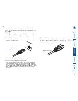
To connect the power adapter

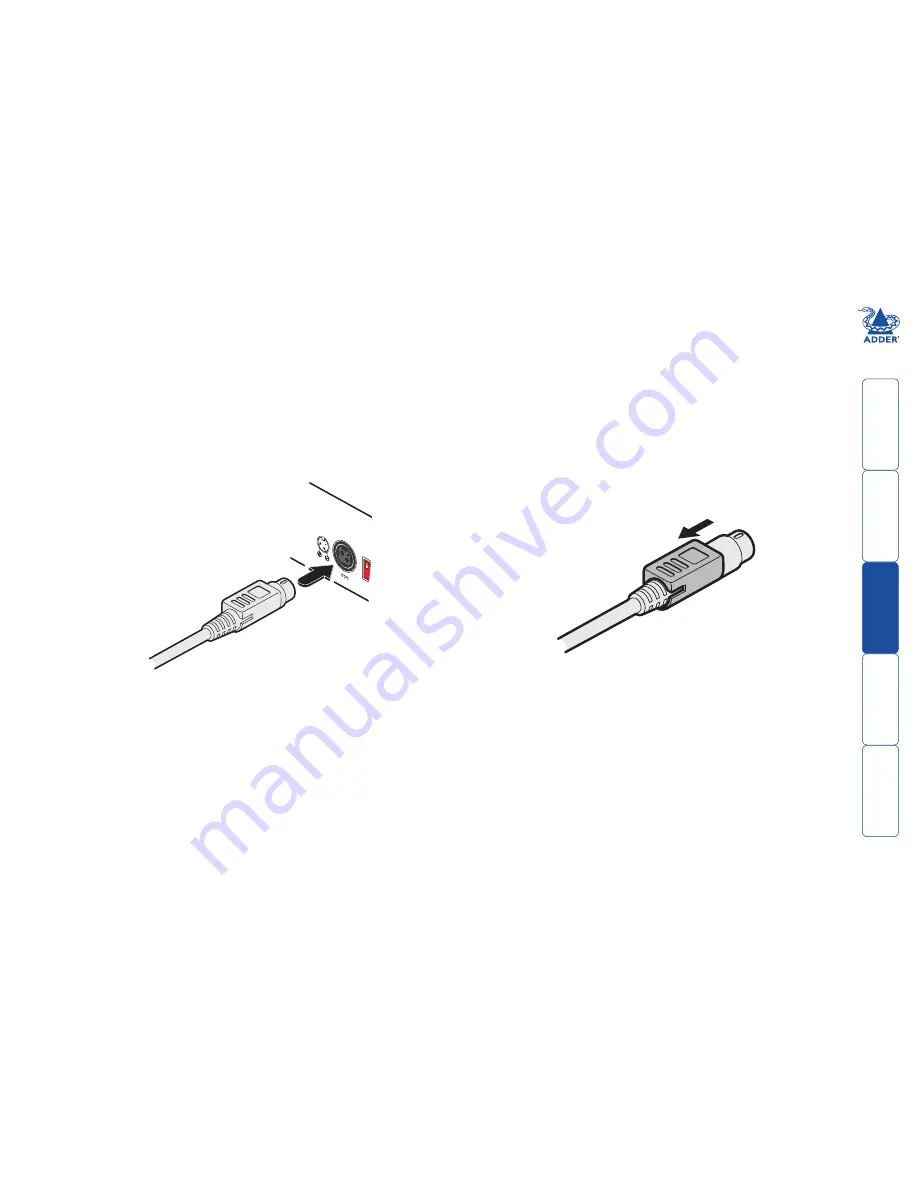
1  Attach the output lead from the power adapter to the 

12V

 socket on the 

rear panel of the rack drawer:

12V

5A

1

ON

2

Connecting the power adapter 
to the rear panel power socket.

Disconnecting the power 
adapter.

2  Connect the IEC connector of the supplied country-specific power lead to 

the socket of the power adapter.

3  Connect the power cord to a nearby power outlet.

  Note: Both the 

rack drawer

 and the power adapter generate heat when 

in operation and will become warm to the touch. Do not enclose them or 
place them in locations where air cannot circulate to cool the equipment. Do 
not operate the equipment in ambient temperatures exceeding 35

o

C. Do not 

place the products in contact with equipment whose surface temperature 
exceeds 35

o

C.


To disconnect the power adapter 

When removing the power connection be aware that the plug has a locking 
mechanism to prevent accidental disconnects. To remove, pull back the flat top 
segment of the plug body to disengage the lock and gently pull the whole plug 
from the power socket:

Summary of Contents for AdderView RDX Rack Drawer

Page 1: ...AdderView RDX Rack Drawer User Guide ...

Page 2: ...etwork or remote user 5 Computer access module links 5 Power connection 6 Initial configuration 7 Operation Opening and closing the rack drawer 8 Operating the rack drawer 9 The screen controls 9 Using the OSD menu 9 Selecting server channels 10 Further information Troubleshooting 11 Screen specifications 11 Getting assistance 11 Warranty 12 Safety information 12 Radio frequency energy 13 ...

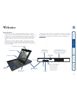
Page 3: ...d within your rack drawer These other guides are stored on the CD ROM supplied with your rack drawer and are also available on the Adder website Carry handle to release the two point lock Clear LCD display screen Switch for screen auto power off Keyboard and mouse touchpad Display control panel KVM switch with connections at the rear INDOOR USE ONLY 4 12 3 11 2 10 1 9 8 16 7 15 6 14 5 13 COMPUTER ...

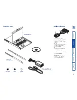
Page 4: ...r connected computer There are four different formats depending on the required computer connections PS 2 style Connectors Analog video PS 2 style keyboard and PS 2 style mouse Part number CATX PS2 USB Connectors Analog video and USB keyboard mouse Part number CATX USB Sun Connectors Analog video Sun keyboard mouse and 3 5mm audio jack Part number CATX SUNA Console CAM for RD1716QIP and RD1916QIP ...

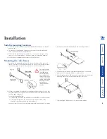
Page 5: ... all eight M6 screws to complete the installation 2 Attach the supplied left and right mounting brackets to the positions in your rack frame where the cage nuts are located and adjust the bracket depths to suit the depth of the rack For each mounting bracket Use two M6 screws and cup washers to fix the bracket to the rear rack rail Use one M6 screw and cup washer only in the lower hole of the brac...

Page 6: ...here are sixteen RJ 45 sockets labelled as COMPUTER CONNECTIONS on the rear panel Each socket supports a CAT 5 5e or 6 link to an individual server system Note The maximum length of the CAM cable can be up to 10 metres 32 feet For models RD1716 and RD1916 also ensure that the overall distance between a remote user connected to a remote extender and any CAM unit server does not exceed 300 metres 98...

Page 7: ...dapter to the rear panel power socket Disconnecting the power adapter 2 Connect the IEC connector of the supplied country specific power lead to the socket of the power adapter 3 Connect the power cord to a nearby power outlet Note Both the rack drawer and the power adapter generate heat when in operation and will become warm to the touch Do not enclose them or place them in locations where air ca...

Page 8: ...r to the Configuration section of the appropriate Adder user guide as appropriate to the rack drawer model being used RDxx16yy use AdderView CATx 1000 user guide RDxx16IPyy use AdderView CATxIP 1000 user guide RDxx16QIPyy use AdderView CATxIP 5000 user guide where xx is either 17 or 19 denoting the LCD screen size yy is the country code e g UK US etc ...

Page 9: ... rack drawer 1 Fold down the screen and locate the black arrow release button on each side of the drawer slider 2 Pull forward and hold the two black arrow buttons while slightly pushing the drawer slider in to release the locks 3 Gently push the drawer slider all the way into the rack using the carry handle Take care to keep your fingers away from the sliders Note for safe use Keep all liquids aw...

Page 10: ...and hold for 5 seconds Exit the OSD menu Also used to toggle digital DVI D and analog SVGA inputs where appropriate Using the OSD menu Press the button to display the OSD menu The various sections within the menu are as follows Image Controls for brightness contrast colour temp red green and blue Geometry Controls for auto adjust H position V position phase and clock Not used Not used Misc Control...

Page 11: ...please refer to the Operation section of the appropriate Adder user guide as appropriate to the rack drawer model being used RDxx16yy use AdderView CATx 1000 user guide RDxx16IPyy use AdderView CATxIP 1000 user guide RDxx16QIPyy use AdderView CATxIP 5000 user guide where xx is either 17 or 19 denoting the LCD screen size yy is the country code e g UK US etc ...

Page 12: ...image Auto adjust can also be initiated within the geometry section of the OSD menu Adjust the H position and V position settings via the OSD menu Getting assistance If you are still experiencing problems after checking the list of solutions in the Troubleshooting section then we provide a number of other solutions Adder Technology website www adder com Check the Support section of our website for...

Page 13: ... use the power adapter if the power adapter case becomes damaged cracked or broken or if you suspect that it is not operating properly Do not attempt to service the unit yourself Not suitable for use in hazardous or explosive environments or next to highly flammable materials If you use a power extension cable make sure the total ampere rating of the devices plugged into the extension cable do not...

Page 14: ... is connected d Consult the supplier or an experienced radio TV technician for help FCC compliance statement United States This equipment generates uses and can radiate radio frequency energy and if not installed and used properly that is in strict accordance with the manufacturer s instructions may cause interference to radio communication It has been tested and found to comply with the limits fo...

Page 15: ...r Way Bar Hill Cambridge CB23 8SQ United Kingdom Tel 44 0 1954 780044 Fax 44 0 1954 780081 Adder Corporation 350R Merrimac Street Newburyport MA 01950 United States of America Tel 1 888 932 3337 Fax 1 888 275 1117 www ctxd com Documentation by Adder Asia Pacific 6 New Industrial Road Hoe Huat Industrial Building 07 01 Singapore 536199 Tel 65 6288 5767 Fax 65 6284 1150 ...

Reviews: