PA 358
Technical description Chapter 8
28
8.3 Watchdog
and
reset
The
PA 358
board is equipped with a watchdog circuitry, which you can enable
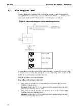
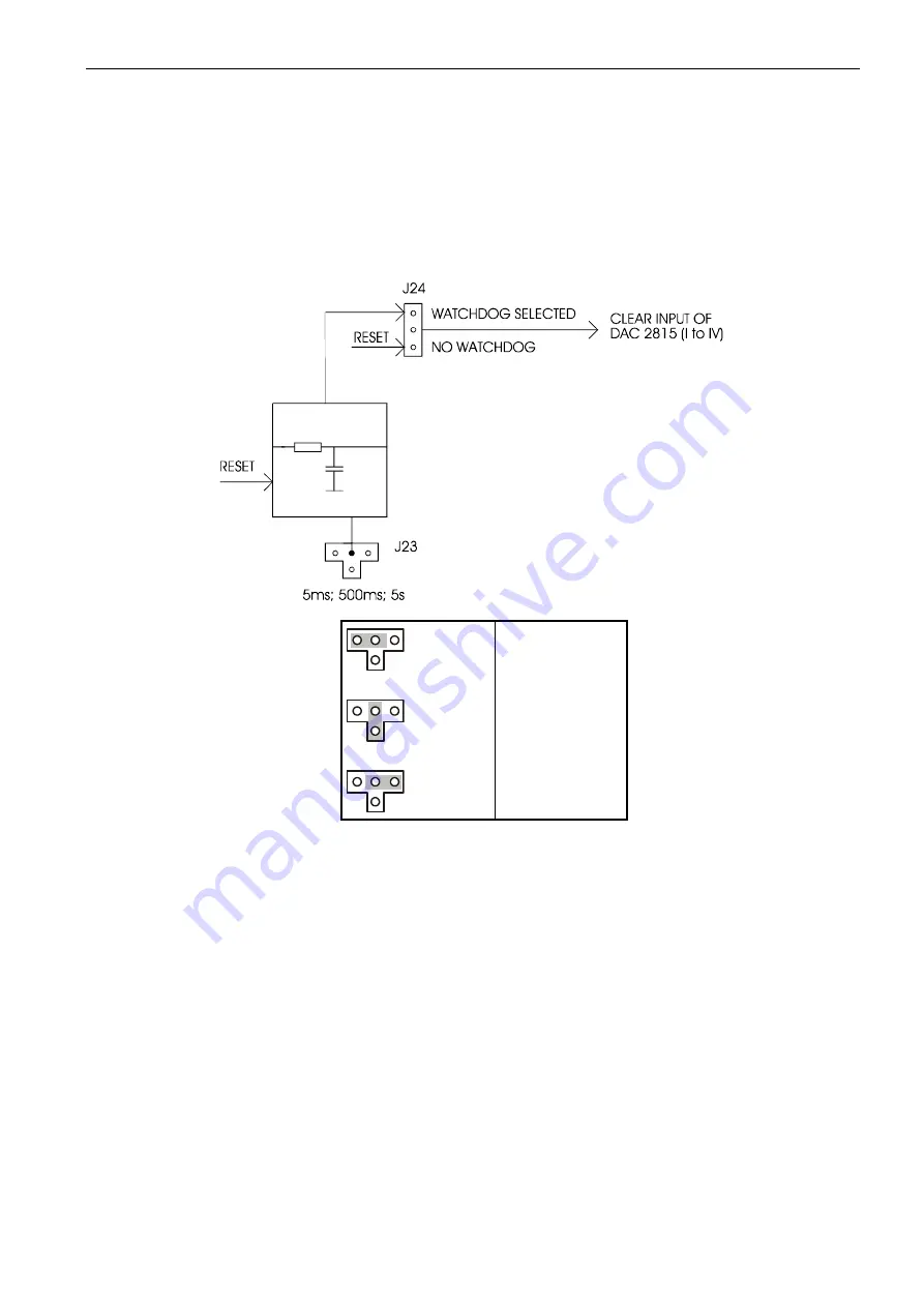
through J24. Three different times are available (5 ms, 500 ms, 5 s), which you can
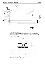
jumper-select through J23. The schematic circuit diagram is as follows:
Fig. 8-2: Schematic diagram of the watchdog circuitry
Time: 5 ms
Time: 500 ms
Time: 5 s
If within the selected time none of the output channels is accessed, i.e no new value
is written on one of them, then all outputs are reset, depending on the adjustment [J1,
J6, J11, J16], to Unipolar zero or Bipolar zero.
One jumper adjusts two output channels.
Depending on the jumper adjustment
•
If the jumper is set, then the corresponding unit is loaded after reset with
0000Hex (Unipolar zero).
Example:
If the range ± 10 V is selected, then the output voltage obtained
after reset or watchdog time is - 10 V.
•
If the jumper is not set, then the corresponding unit is loaded with the value
0800Hex after reset (Bipolar Zero).
Example:
If the range ± 10 V is selected, then the output voltage obtained
after reset or watchdog time is 0 V.

