PA 7400
Technical description Chapter 8
38
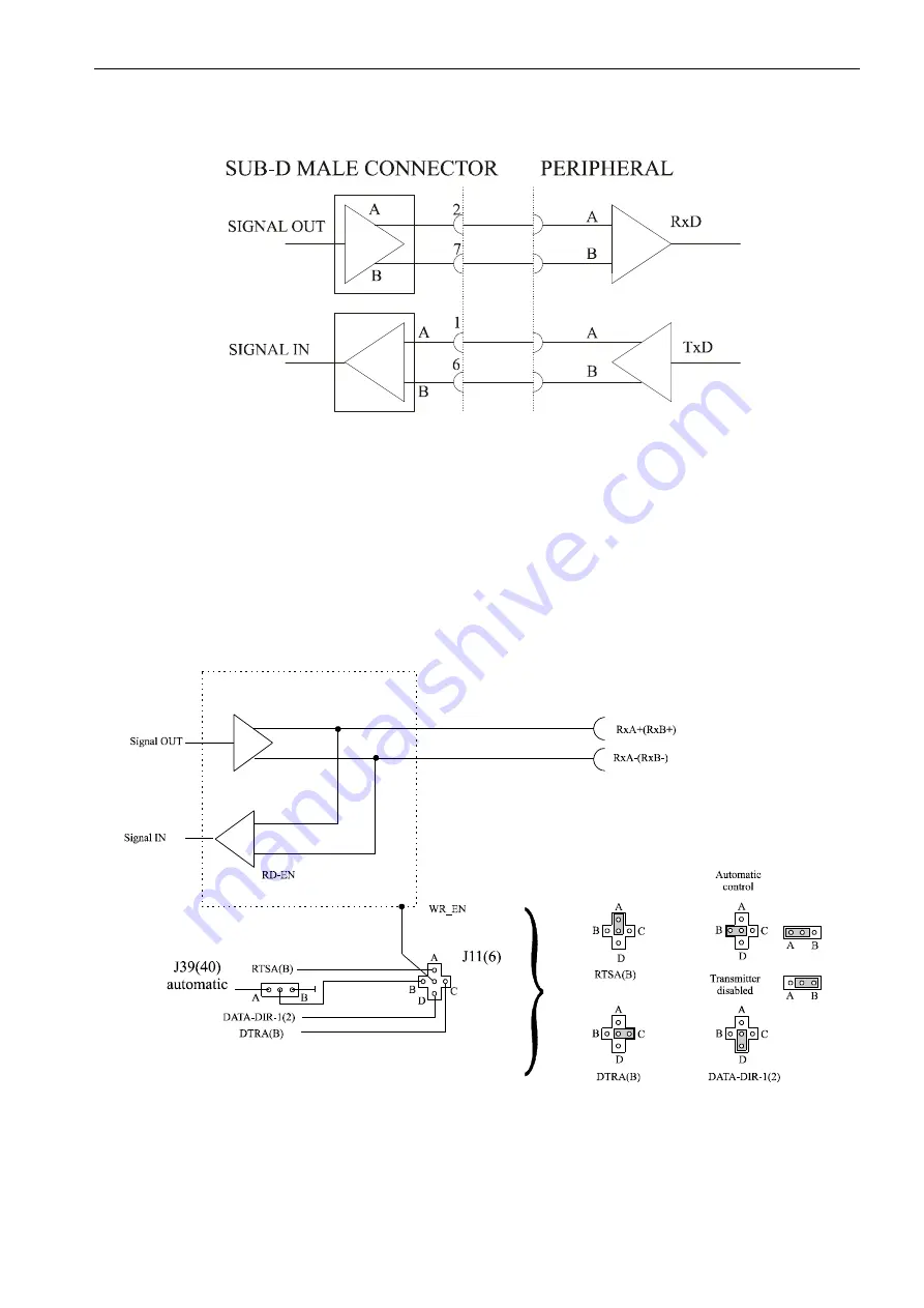
Fig. 8-7: RS 422 cabling for serial port 2
8.3.3 RS485
Controlling the RS 485 transmitter
Refer to Chapter 5.2 Jumper settings and functions
Fig. 8-8: Enabling the automatic transmitter with the signals DTRA(B), RTSA(B)
or DATA-DIR-1(2) through jumper J11(6)
•
Make sure
that the values of data bits D2-D7 are not overwritten when writing
in the MODEM CONTROL REGISTER A(B) on
Base-S1(2) +4
.


