background image


Product information 
This manual contains the technical installation and important instructions for correct commissioning and 
usage, as well as production information according to the current state before printing. 
The content of this manual and the technical product data may be changed without prior notice.  
ADDI-DATA GmbH reserves the right to make changes to the technical data and the materials included 
herein. 

Warranty and liability 
The user is not authorised to make changes to the product beyond the intended use, or to interfere with 
the product in any other way. 
ADDI-DATA shall not be liable for obvious printing and phrasing errors. 
In addition, ADDI DATA, if legally permissible, shall not be liable for personal injury or damage to 
materials caused by improper installation and/or commissioning of the product by the user or improper 
use; for example, if the product is operated despite faulty safety and protection devices, or if notes in the 
operating instructions regarding transport, storage, installation, commissioning, operation, limit values, 
etc. are not taken into consideration. 
Liability is further excluded if the operator changes the product or the source code files without 
authorisation and/or if the operator is guilty of not monitoring the permanent operational capability of 
working parts and this has led to damage. 

Copyright 
This manual, which is intended for the operator and its staff only, is protected by copyright. Duplication 
of the information contained in the operating instructions and of any other product information, or 
disclosure of this information for use by third parties, is not permitted, unless this right has been granted 
by the product licence issued. Non-compliance with this could lead to civil and criminal proceedings. 

ADDI-DATA software product licence 
Please read this licence carefully before using the standard software! The customer is only granted the 
right to use this software if he/she agrees with the conditions of this licence. 
The software may only be used to set up the ADDI-DATA products. 
Reproduction of the software is forbidden (except for back-up and for exchange of faulty data carriers). 
Disassembly, decompilation, decryption and reverse engineering of the software are forbidden. This 
licence and the software may be transferred to a third party if this party has acquired a product by 
purchase, has agreed to all the conditions in this licence contract and the original owner does not keep 
any copies of the software. 

Trademarks 


ADDI-DATA, APCI-1500, MSX-Box and MSX-E are registered trademarks of ADDI-DATA GmbH. 


Turbo Pascal, Delphi, Borland C, Borland C++ are registered trademarks of Borland Software 
Corporation. 


Microsoft .NET, Microsoft C, Visual C++, MS-DOS, Windows XP, Windows 7, Windows 10,  
Windows Server 2000, Windows Server 2003, Windows Embedded and Internet Explorer are registered 
trademarks of Microsoft Corporation. 


Linux is a registered trademark of Linus Torvalds. 


LabVIEW, LabWindows/CVI, DASYLab, DIAdem are registered trademarks of National Instruments 
Corporation. 


CompactPCI is a registered trademark of PCI Industrial Computer Manufacturers Group. 


VxWorks is a registered trademark of Wind River Systems, Inc. 


RTX is a registered trademark of IntervalZero. 


Summary of Contents for APCI-1648

Page 1: ... DATA GmbH Airpark Business Center Airport Boulevard B210 77836 Rheinmünster Germany Phone 49 7229 1847 0 Fax 49 7229 1847 222 E mail info addi data com www addi data com Technical description APCI 1648 APCI 1696 TTL I O board ADDI DATA PARTNER FÜR PRÄZISION ...

Page 2: ...ions and of any other product information or disclosure of this information for use by third parties is not permitted unless this right has been granted by the product licence issued Non compliance with this could lead to civil and criminal proceedings ADDI DATA software product licence Please read this licence carefully before using the standard software The customer is only granted the right to ...

Page 3: ...tact us and ask for it Observe the instructions of this manual Make sure that you do not forget or skip any step We are not liable for damages resulting from the wrong use of the board Pay attention to the following symbols NOTICE Designates hints and other useful information NOTICE Designates a possibly dangerous situation If the instructions are ignored the board the PC and or peripherals may be...

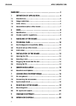
Page 4: ...atibility EMC 10 4 2 Physical set up of the board 10 4 3 Limit values 11 5 INSTALLATION OF THE BOARD 13 5 1 Opening the PC 13 5 2 Selecting a slot 13 5 3 Plugging the board into the slot 14 5 4 Closing the PC 14 6 DRIVER INSTALLATION 15 6 1 Questions and Updates 15 7 CONNECTING THE PERIPHERALS 16 7 1 Pin assignment 16 7 2 Connecting the accessories 17 7 3 Input output circuit 18 8 FUNCTIONS OF THE...

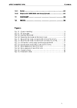
Page 5: ...3 Fastening the board at the back cover 14 Fig 7 1 50 pin D Sub male connector TTL I O 0 to TTL I O 47 16 Fig 7 2 50 pin D Sub male connector TTL I O 48 to TTL I O 95 16 Fig 7 3 Connection of the screw terminal panel PX8001 17 Fig 7 4 Input output circuit APCI 1648 or APCI 1696 18 Fig 8 1 Block diagram of the APCI 1648 19 Fig 8 2 Block diagram of the APCI 1696 19 Fig 10 1 Serial number 22 Fig 10 2...

Page 6: ...ssemblies 1 2 Usage restrictions The boards APCI 1648 and APCI 1696 must not be used as safety related parts SRP The boards must not be used for safety related functions for example for emergency stop functions The boards APCI 1648 and APCI 1696 must not be used in potentially explosive atmospheres The boards APCI 1648 and APCI 1696 must not be used as electrical equipment according to the Low Vol...

Page 7: ...he 50 pin D Sub male connector of the board The board has 48 or 96 bidirectional input output channels for processing TTL signals The PX8001 screw terminal board allows the connection of the digital signals with a shielded cable The connection with our standard cable ST370 16 complies with the following specifications metallised plastic hoods shielded cable cable shield folded back and firmly scre...

Page 8: ...ectronics are entitled to perform the following works installation commissioning use maintenance 2 2 Country specific regulations Consider the country specific regulations about the prevention of accidents electrical and mechanical installations Electromagnetic compatibility EMC ...

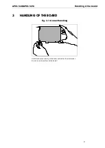
Page 9: ...APCI 1648 APCI 1696 Handling of the board 9 3 HANDLING OF THE BOARD Fig 3 1 Correct handling Hold the board cautiously at the outer end and at the slot bracket Do not touch the surface of the board ...

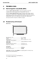
Page 10: ...ective for an industrial environment are complied with The respective EMC test report is available on request 4 2 Physical set up of the board Dimensions Dimensions L x W 127 x 80 mm Weight approx 160 g Installation in PCI 32 bit slot 3 3 V 5 V Connection to the peripherals APCI 1648 50 pin D Sub male connector APCI 1696 50 pin D Sub male connector TTL I O 0 to 47 50 pin male connector TTL I O 48 ...

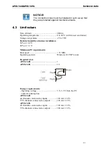
Page 11: ...to 70 C Relative humidity at indoor installation 50 at 40 C 80 at 31 C Minimum PC requirements Bus speed 33 MHz Operating system Windows 10 7 XP Linux Required slots APCI 1648 1 APCI 1696 1 1 Energy requirements Operating voltage 5 V 3 3 V from the PC Current consumption APCI 1648 all channels connected as inputs 100 mA 10 TTL channels connected as outputs 100 mA 10 APCI 1696 all channels connecte...

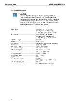
Page 12: ...TTL inputs and outputs 6 independent modules with each 8 TTL input output channels APCI 1696 96 TTL inputs and outputs 12 independent modules with each 8 TTL input output channels I O address range 128 bytes Access 8 bit 32 bit Programming through I O read or write commands Driver type 74ALVC164245 Min output voltage 3 84 V High level Max output voltage 0 1 V Low level TTL input compatible 0 8 V m...

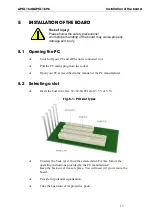
Page 13: ...l the PC mains plug from the socket Open your PC as described in the manual of the PC manufacturer 5 2 Selecting a slot Insert the board in a free 32 64 bit PCI slot 3 3 V or 5 V Fig 5 1 PCI slot types Unscrew the back cover from the selected slot For this follow the operating instructions provided by the PC manufacturer Keep the back cover in a safe place You will need it if you remove the board ...

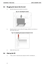
Page 14: ...rtically into the chosen slot Fig 5 2 Inserting the board Fasten the board to the rear of the PC housing with the screw which was fixed on the back cover Fig 5 3 Fastening the board at the back cover Tighten all loose screws 5 4 Closing the PC Close your PC as described in the manual of the PC manufacturer ...

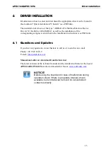
Page 15: ... the installation instructions see PDF link 6 1 Questions and Updates If you have any questions do not hesitate to call us or to send us an e mail Phone 49 7229 1847 0 E mail info addi data com Manual and software download from the Internet The latest versions of the technical manual and the standard software for the board APCI 1648 APCI 1696 can be downloaded for free at www addi data com NOTICE ...

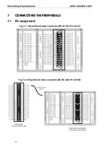
Page 16: ...ng the peripherals APCI 1648 APCI 1696 16 7 CONNECTING THE PERIPHERALS 7 1 Pin assignment Fig 7 1 50 pin D Sub male connector TTL I O 0 to TTL I O 47 Fig 7 2 50 pin D Sub male connector TTL I O 48 to TTL I O 95 ...

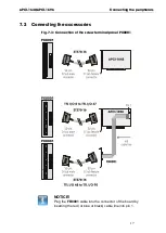
Page 17: ...ing the peripherals 17 7 2 Connecting the accessories Fig 7 3 Connection of the screw terminal panel PX8001 NOTICE Plug the FB8001 cable into the connector of the board by inserting the red or blue or black cable line into pin 1 ...

Page 18: ...Connecting the peripherals APCI 1648 APCI 1696 18 7 3 Input output circuit Fig 7 4 Input output circuit APCI 1648 or APCI 1696 ...

Page 19: ...APCI 1648 APCI 1696 Functions of the board 19 8 FUNCTIONS OF THE BOARD 8 1 Block diagrams Fig 8 1 Block diagram of the APCI 1648 Fig 8 2 Block diagram of the APCI 1696 ...

Page 20: ...odule includes 8 channels and can be configured either as input or output Up to 20 LSTTL loads can be controlled through the TTL outputs The combination of several inputs and outputs allows data to be exchanged in parallel and bidirectionally with various peripheral devices NOTICE The outputs are not protected against short circuits ...

Page 21: ...DARD SOFTWARE The API software functions supported by the board are listed in an HTML document A description of how to access the respective file can be found in the document Quick installation PC boards see PDF link in the chapter Standard software ...

Page 22: ...ne extension and e mail address as well as the mailing address for a potential new delivery You do not have to indicate the RMA number Fig 10 1 Serial number Note down the serial number of the board Place the board in an ESD protective cover Then pack it in a cardboard box so that it is well protected for shipping Send the packed board together with your details to ADDI DATA GmbH Airpark Business ...

Page 23: ... other European countries that have a separate collection system Products carrying this symbol must not be treated as household waste For more detailed information on the recycling of these products please contact your local citizens office your household waste collection service the shop where you bought this product or the distributor you purchased this product from If you dispose of this produc...

Page 24: ... A signal which has distinct states Digital computers process data as binary information having either 1 or 0 states Disturb signal Interferences that occur during the transfer caused by reduced bandwidth attenuation gain noise delay time etc Driver A part of the software that is used to control a specific hardware device such as a data acquisition board or a printer Gain The factor by which an in...

Page 25: ...be derived that are required for example in current supplies and in other electronic circuitries Resolution The smallest significant number to which a measurement can be determined For example a converter with 12 bit resolution can resolve 1 part in 4096 Sensor A device that responds to physical stimuli heat light sound pressure motion etc and produces a corresponding electrical output Settling ti...

Page 26: ...c compatibility 10 Energy requirements 11 G Glossary 24 H Handling 9 I Installation of the board 13 Intended use 6 L Limit values 11 P Pin assignment 16 R Repair 22 Return 22 S Slots required 11 Standard software 21 T TTL inputs and outputs Function description 20 U Update Driver 15 Manual 15 Usage restrictions 6 User Qualification 8 W Weight 10 ...

Reviews: