APCI-3003 Technical
data
Acquisition types: ......................................1) Simple mode
2) Scan mode
3) Sequence mode
4) Auto refresh mode
Conversion start: ........................................1) software trigger
2)
external
trigger
3)
trigger
timer
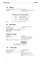
Analog input ranges (adjustable by software):
Voltage:......................................................Unipolar: 0-10
V
1 LSB: 153 µv
Bipolar:
± 10 V (selectable by
software)
1 LSB: 305 µv
Current (optional):......................................Unipolar:
0-20 mA
(When
Unipolar,
gain = 2)
Gain:...........................................................Gain 1, 2, 5, 10 (Gain is configurable
....................................................................through software)
Overvoltage protection:..............................+/- 40 V
2
Bandwith (-3 dB): ......................................Limited to 212.2 kHz (-3 dB) with
....................................................................lowpass filter first level
Input impedance:........................................10
12
Ω
|| 5 nF
Digital codification: ...................................linear
Analog Input
Binary Code
HEX Code
Bipolar Unipolar
- 10V
0V
0000000000000000
0000
0V
5 V
1000000000000000
8000
+10 V
10 V
1111111111111111
FFFF
Optical isolation from the PC:....................1000 V
Temperature drift: ......................................10 ppm/K
Linearity error of the ADC:........................±1.22 mV (typ.)
±2.44 mV (max.)
Calibration of the inputs:
Bipolar offset calibration value:.................-0.00061 V (tolerance: ±0.0017 V)
Unipolar offset calibration value:...............0.01 V (tolerance: ±0.0017 V)
Bipolar gain calibration value:...................9.995 V (tolerance: ±0.0017 V)
Unipolar gain calibration value:.................9.995 V (tolerance: ±0.0017 V)
Calibration channel: ...................................0
Measurement method:................................Averaging of more than 200 values
13

