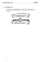
Functions of the board
APCI-3003
Please note: During the switching of the voltage range from unipolar to bipolar or
from bipolar to unipolar there is a longer settling time of the measuring chain (see
chapter
Fehler! Verweisquelle konnte nicht gefunden werden.
).
8.2.3
Analog input switch
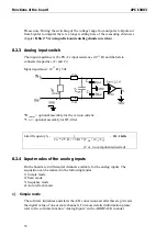
The input impedance is the PGA’s input resistance (10
12
Ω
) and the hereto
connected capacities (C
1
and C
2
).
Input impedance= 10
12
Ω
|| 5 nF
*R
current
= optional assembly for the version current.
*C
DF
= optional assembly for DF-filter
Limit frequency f
g =
1
=
212. 2 KHz
2
п
* (75
Ω
+ 75
Ω
) * [C
DF
+ (C
1
||C
2
]
(C
DF :
no components inserted)
8.2.4
Input modes of the analog inputs
On the board are 4 differential channels available for the analog inputs. The
acquisition can be realized in the following modes
1) Simple mode
2) Scan mode
3) Sequence mode
4) Auto refresh mode
1)
Simple mode
The software initializes and starts the A/D conversion and after this step it reads
the digital value of one or more channels. For more detailed information please
refer to the software function “Analog Inputs” in the ADDIPACK manual
32

